

Related Articles
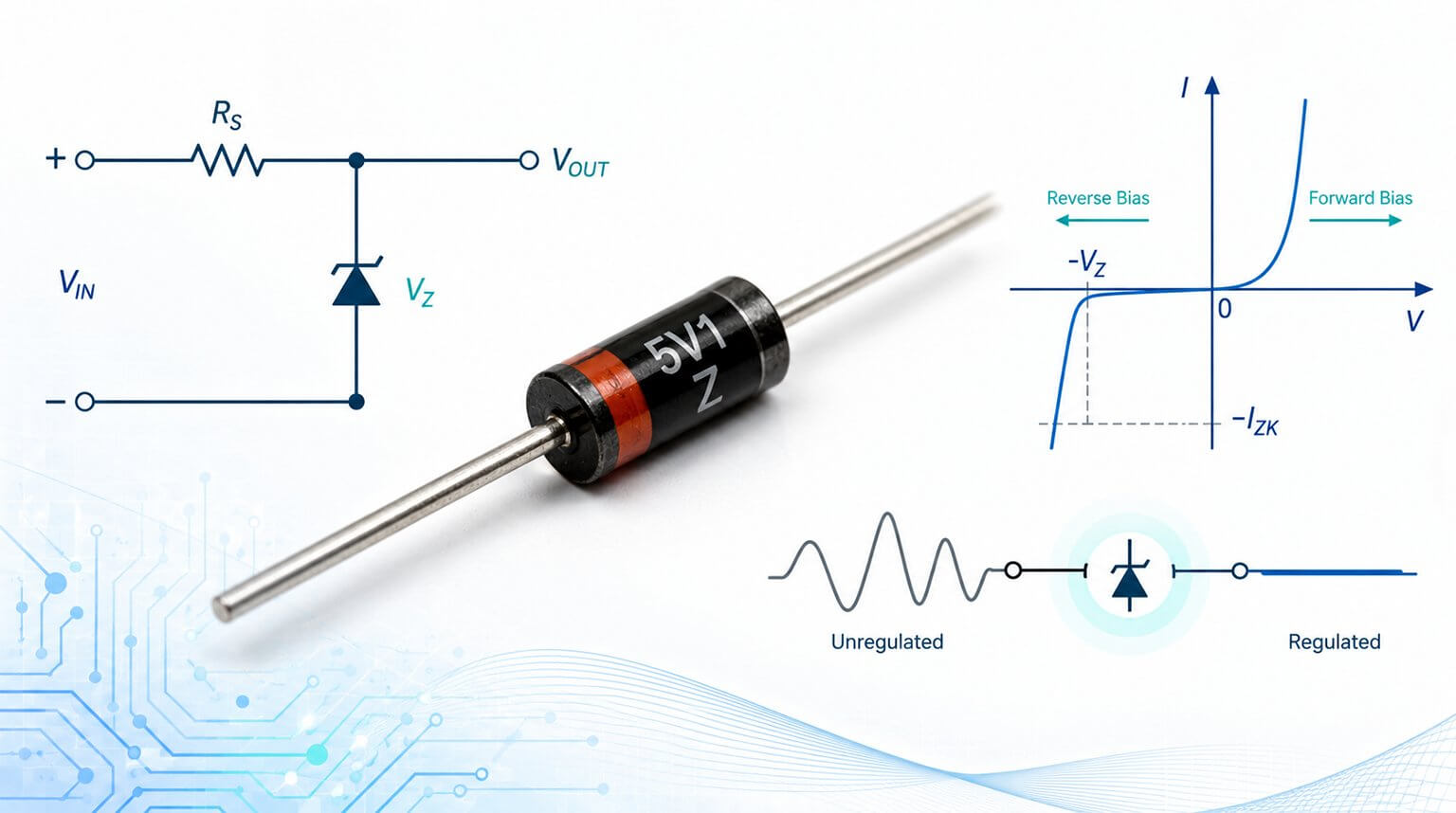
Everything You Need to Know About Zener Diodes
A Zener diode is a specially doped p-n junction diode designed to operate in reverse breakdown and maintain a stable voltage.
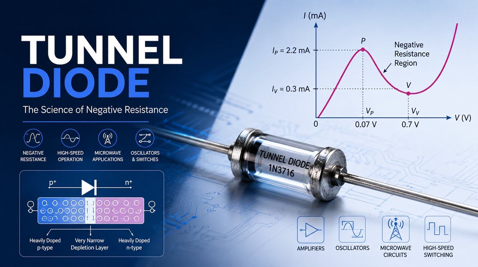
Complete Guide to Tunnel Diodes
A tunnel diode is a heavily doped p-n junction diode that uses quantum tunneling to produce negative resistance. This guide explains its working principle, characteristics, and applications.
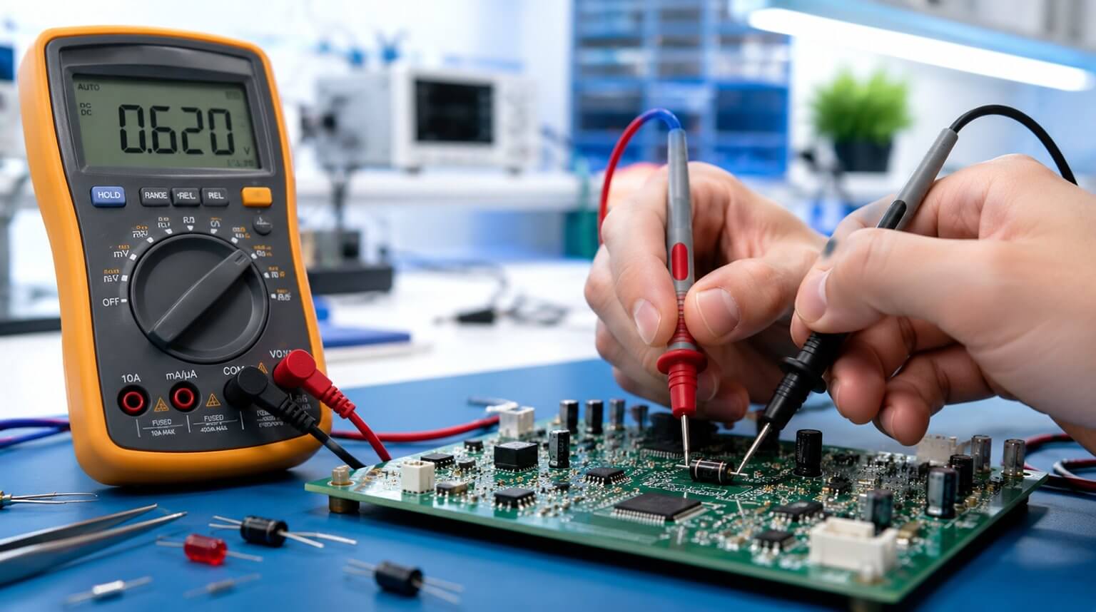
How to Test a Diode to Determine If It Is Bad
Test a diode in forward and reverse bias. A good diode shows a normal forward voltage drop and blocks current in reverse; abnormal readings usually indicate a bad diode.
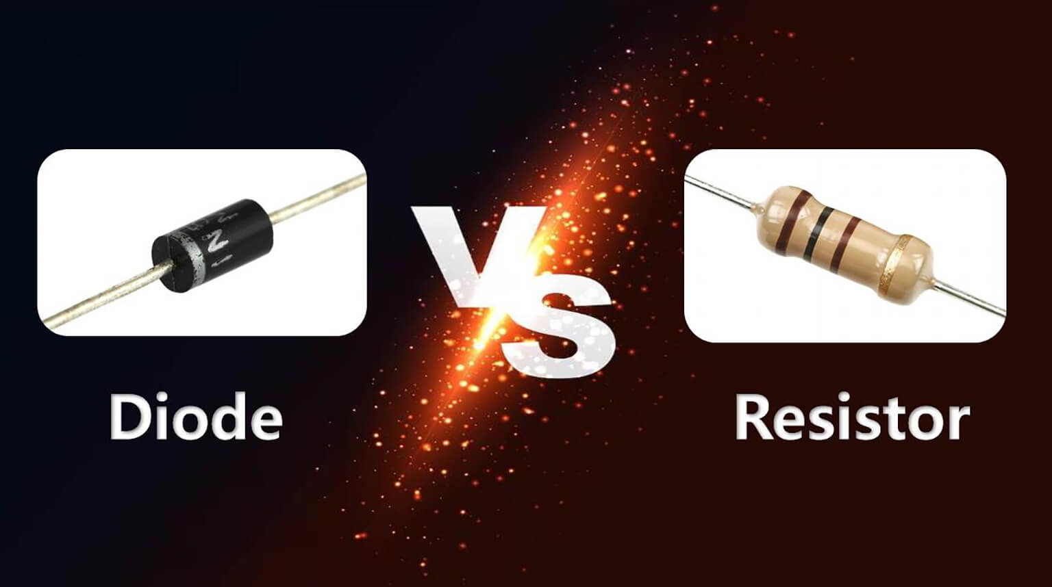
The Difference Between Diodes and Resistors
A diode is a semiconductor component that mainly allows current to flow in one direction, while a resistor is a passive component that limits current in a circuit.

What Causes a Capacitor to Fail
Understand how capacitors fail in real circuits, how to identify early warning signs, and how better component sourcing and PCBA assembly help improve product reliability.
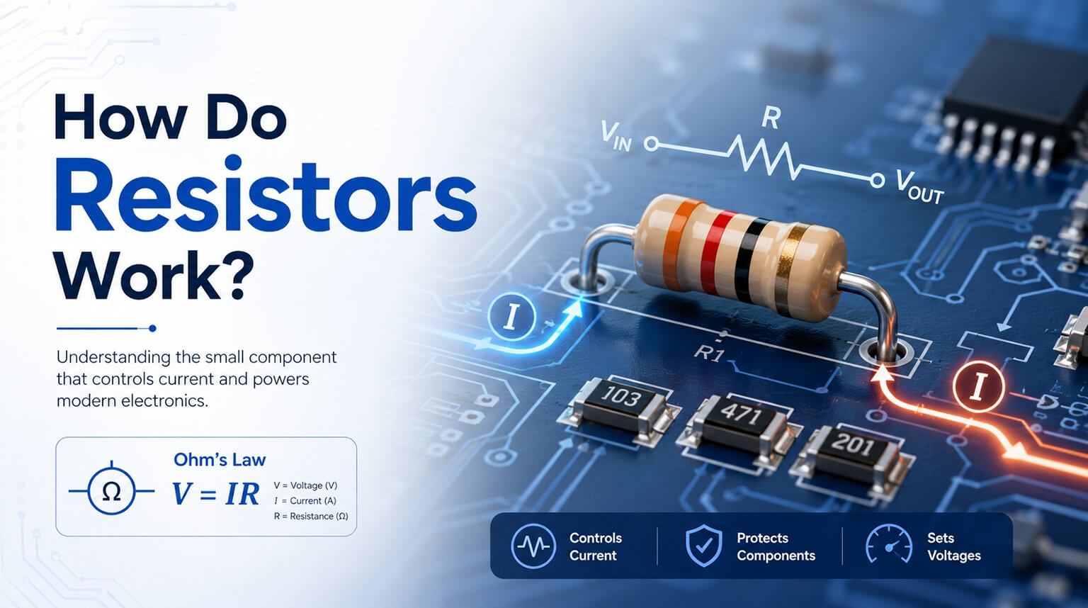
What Is a Resistor and How Does It Work
Understand how resistors work in real circuits, why they oppose current flow, how Ohm’s Law applies, and how the right resistor supports stable PCB design.

How to Discharge a Capacitor
Learn how to discharge a capacitor safely with a resistor, discharge tool, and multimeter verification. Follow practical safety steps before handling capacitors.
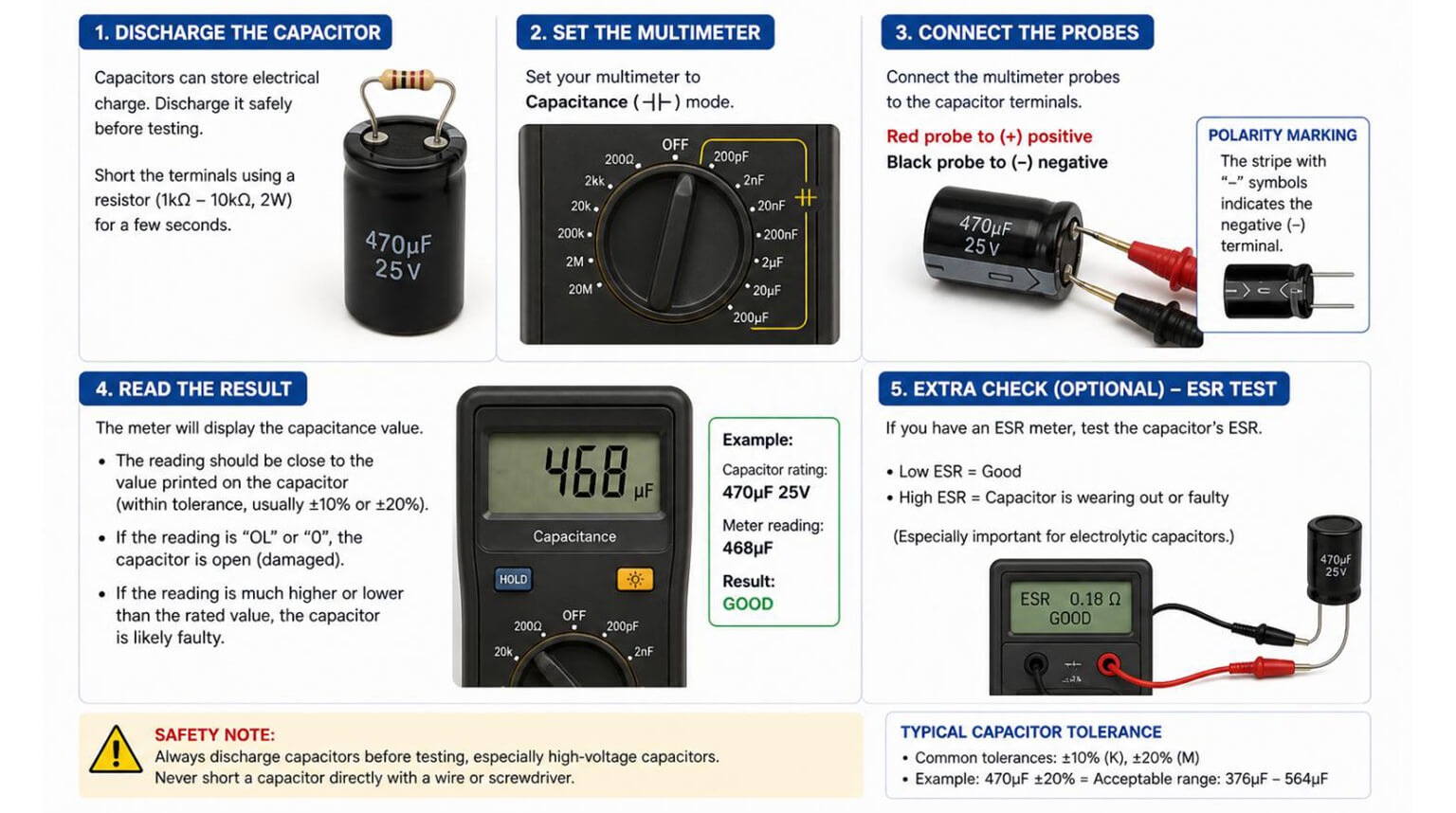
How to Test a Capacitor
Learn how to test a capacitor and check if it is bad using a multimeter, ESR meter, LED test, and oscilloscope. Includes safety steps, failure signs, and replacement tips.

Introduction to 7 Different BGA Package Types
Explore 7 BGA package types and learn how they differ in structure, pitch, density, thermal performance, and manufacturing impact for better package selection.
What Does BGA Mean in Electronics
Learn what BGA is, why it is widely used in modern electronics, how different BGA package types compare, and what matters most in BGA assembly and inspection.
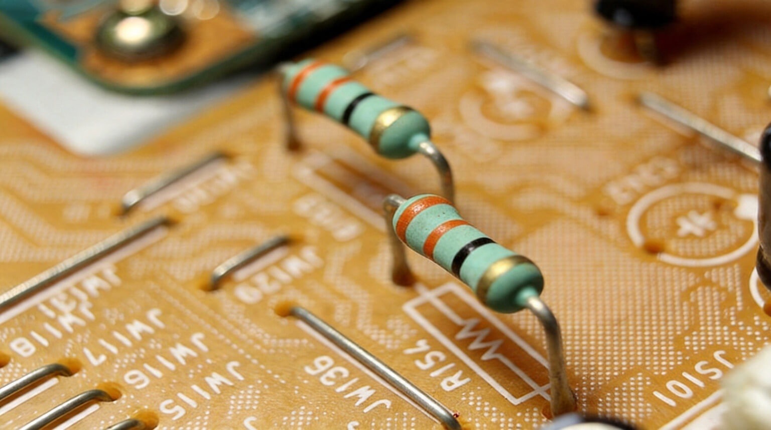
How to Test a Resistor
Learn how to test a resistor accurately using a multimeter, in-circuit methods, TCR checks, and failure screening. Practical tips for reliable resistor testing.
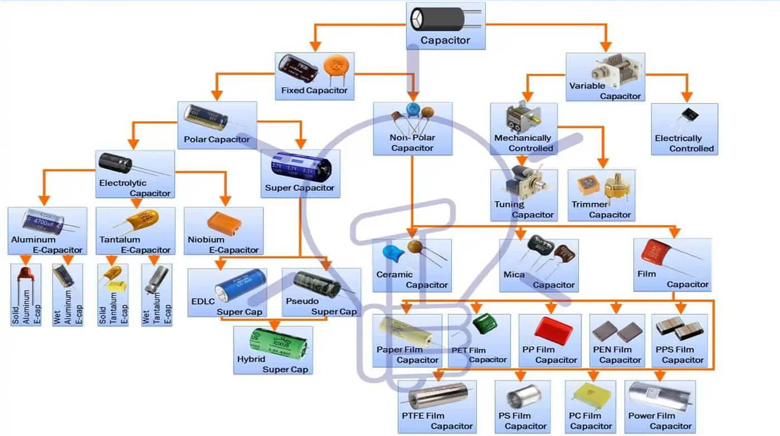
An Introduction to Different Types of Capacitors
This article covers four common capacitor types—tantalum, aluminum electrolytic, glass, and ceramic—and explains their pros, cons, and typical applications.
