When designing a DDR4 PCB or DDR4 memory interface, engineers often focus on terms such as timing control, impedance matching, and careful component placement. These concepts are important, but they are too broad to guide a real layout on their own.
In practice, many DDR4 layout problems come from treating the interface as one uniform bus. A DDR4 interface is better understood as a collection of different signal groups, including DQ/DQS byte lanes, address and command signals, clock pairs, control signals, reference voltages, and power rails.
Each group has its own timing relationship, routing topology, impedance requirement, and noise sensitivity. That is why DDR4 layout cannot rely on one general rule applied across the entire interface.
At 2400 MT/s to 3200 MT/s, the unit interval is only about 417 ps to 313 ps. On a typical FR-4 stackup, signal propagation delay is often around 150–170 ps per inch, depending on trace geometry and dielectric properties. As a result, even small routing differences can create measurable skew, especially within DQ/DQS byte lanes.
A practical DDR4 layout strategy should therefore start by separating the interface into functional signal groups and applying routing rules specific to each group. Length tuning should be based on electrical delay and the memory controller’s layout constraints, not simply on visual symmetry.
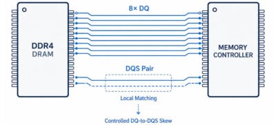
The DDR4 data bus is organized into byte lanes. Each byte lane contains eight DQ signals and one differential DQS pair. This byte-lane structure is important and should be preserved in the physical layout.
The DQS pair acts as the timing reference for its associated DQ signals. During read and write operations, data is sampled based on DQS timing rather than the global clock. For this reason, the most critical timing parameter within a byte lane is the skew between DQ and DQS.
On a typical PCB stackup, signal propagation delay is around 160 ps/inch, or about 6–7 ps/mm. If the memory controller allows only ±20 ps of skew within a byte lane, just a few millimeters of mismatch can consume much of the available timing budget. Therefore, routing within each byte lane should be compact, direct, and preferably kept on the same layer.
Length matching should be handled locally within each byte lane. There is no need to match DQ signals from one byte lane to another, because DDR4 training logic can compensate for each lane separately. Trying to match all data signals globally often increases routing congestion and creates unnecessary serpentine patterns, which can introduce coupling and impedance deviation.
Serpentine tuning should be used only when necessary and should be carefully controlled. Dense zig-zag patterns create closely spaced parallel segments, increasing capacitive coupling and worsening impedance consistency. When meanders are needed for length tuning, they should be smooth, widely spaced, and kept away from critical coupling areas.
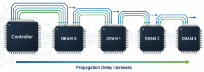
DDR4 address and command signals use a fly-by topology, unlike data lanes, which are routed in a point-to-point structure. Each signal leaves the memory controller and passes sequentially through the DRAM devices. Because of this fly-by structure, additional propagation delay is introduced from one DRAM device to the next.
This means the signals do not arrive at all DRAM devices at exactly the same time. In other words, absolute length equality is not the goal for address and command routing.
Skew tolerance for address and command signals is typically much wider than for DQ signals, often in the range of ±40 ps to ±60 ps depending on the memory controller. However, the more important requirement is consistent routing order. All address and command lines should follow the same physical sequence across the memory devices.
If one signal creates a separate branch, or routes around a DRAM pad differently from the others, the consistency of the fly-by path can be lost. This can create timing behavior that is harder for the controller to predict and compensate for.
Single-ended impedance targets usually remain in the 40–50 Ω range. Because fly-by routing places multiple loads along each signal path, the via structure should also be clean and consistent. A stable via topology helps the signals behave predictably along the entire route.
The global timing reference for the DDR4 memory interface is provided by a differential clock pair. Tight intra-pair matching and stable differential impedance, typically 100 Ω, are required. Any mismatch between the positive and negative traces can cause mode conversion, adding jitter and EMI to the signal.
Clock routing should also minimize vias wherever possible. Each via introduces parasitic inductance and capacitance. On thicker boards, unused via barrel sections can form stubs, which may resonate within frequency ranges relevant to DDR4 operation. In critical designs, back-drilling may be required to remove these stubs.
Both traces of a differential clock pair should remain referenced to the same continuous ground plane. Plane splits should not pass under only one trace of the pair, because this creates asymmetry and degrades signal quality. Consistent spacing between the two traces is also important for maintaining stable differential impedance.
Clock routing is different from DQ-to-DQS matching. The clock pair functions as a distributed timing reference for the interface, so it must remain electrically clean along the entire route, not just matched locally.
Control signals such as RESET, CKE, CS, and ODT do not require the same tight skew matching as DQ signals because they operate outside byte-lane timing relationships. These signals usually toggle at a lower rate, so the layout focus is different from DQ/DQS routing.
Controlled impedance routing, typically in the 40–50 Ω range, is still necessary. However, tight length matching is not usually the main concern. The priority should be clean routing, minimal stubs, and continuous reference planes.
ODT requires special attention because it controls on-die termination switching. Although it is not timing-critical in the same way as DQ signals, unstable ODT routing can indirectly affect reflection control during memory transactions.
DDR4 uses dedicated reference voltage circuits for both data signals and address/command signals: VrefDQ for data and VrefCA for address/command. These reference voltages provide the internal comparison threshold used by the DRAM.
Ripple and coupled switching noise on Vref nets directly reduce the available noise margin. For reliable operation, ripple tolerance is typically limited to only a few tens of millivolts. Because of this, Vref routing should be short, isolated from noisy switching signals, and referenced to a low-noise ground.
Vref traces should also avoid long parallel routing near DQ switching bundles. Parallel routing can introduce capacitive coupling and disturb the reference voltage level, especially if decoupling capacitors are not placed close to the DRAM reference pins.
These nets should therefore be treated as sensitive analog reference lines, not as ordinary digital traces.
PCB stackup design has a direct impact on insertion loss and impedance stability. Standard FR-4 materials typically have a dielectric constant (Dk) between 3.8 and 4.2, and a loss tangent (Df) between 0.015 and 0.02. At around 1–2 GHz, insertion loss is often in the range of 0.5 to 1.0 dB per inch, depending on dielectric quality and copper roughness.
Stripline routing between two solid ground planes provides better field containment than outer-layer microstrip routing. This can help maintain more consistent impedance across the route. Using low-profile copper can also reduce conductor loss, which helps improve eye margin at higher data rates.
Manufacturing tolerance should be included in simulation model parameters. For example, a fabrication impedance tolerance of ±10% can affect reflection coefficients and eye width.
During refresh, a single DRAM device may draw current as high as 2–4 A. Read and write operations can also create significant transient current demand. During these rapid current changes, the voltage rail at the point of load must remain within ±5% of nominal voltage, or 1.20 V ±0.06 V.
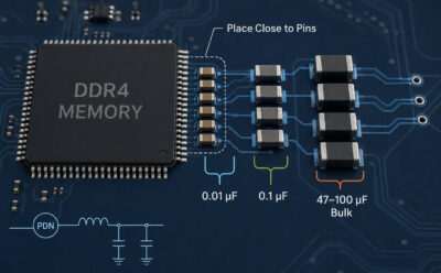
A practical decoupling strategy should combine bulk and ceramic capacitors across different frequency ranges. Bulk capacitors in the 47–100 µF range should be placed near the memory block to provide a charge reservoir for large step changes in current.
For lower impedance in the mid-frequency range, from about 100 MHz to several GHz, 0.1 µF ceramic capacitors should be placed in parallel with the bulk capacitors. For additional high-frequency decoupling above 1 GHz, 0.01 µF ceramic capacitors can also be added close to the same area.
Placement is critical. A 0.1 µF capacitor placed too far from a memory pin will have limited high-frequency decoupling effect because of the inductance in the trace path between the capacitor and the pin. For best results, decoupling capacitors should be placed within 300 mils of the memory pins.
The power delivery network, or PDN, should be verified with an impedance sweep by plotting PDN impedance versus frequency. The target PDN impedance should remain below 0.1 Ω for frequencies above 1 kHz.
Significant capacitive coupling can occur between adjacent parallel traces when the spacing between them is less than two times the trace width. In a dense DDR4 memory layout, this type of coupling is difficult to avoid completely, so it must be controlled through spacing, layer strategy, and shielding.
The amount of coupling between parallel traces depends strongly on signal rise time, or edge rate. Many DDR4 signals have driver rise times in the range of 100–200 ps. With a 100 ps rise time and an estimated coupling capacitance of 4 pF at a 2 mil trace separation, induced crosstalk current on the adjacent trace can approach 10 mA.
To reduce coupling, several DDR4 PCB layout methods can be used:
- Increase trace spacing: Each additional mil of spacing can reduce coupling capacitance by about 0.3 pF/in. For example, increasing separation from 5 mils to 8 mils can reduce crosstalk by approximately 30%.
- Route byte lanes on different layers: For example, if DQ[0:7] is routed horizontally on layer 3, DQ[8:15] can be routed vertically on layer 4. Orthogonal routing helps reduce capacitive coupling between adjacent byte lanes.
- Use grounded guard traces where space allows: Guard traces, tied to ground through stitching vias, can reduce crosstalk by around 50%. However, they require additional routing space and should be used selectively.
Most production designs use a combination of wider spacing and shielding between critical signal groups. The main tradeoff is routing density versus signal integrity.
DDR4 layout is not about applying one universal routing rule across the entire memory interface. It is about understanding how each signal group behaves and giving each one the right layout priority.
When DQ/DQS timing, fly-by routing, clock stability, Vref noise control, stackup selection, power integrity, and crosstalk management are handled together, DDR4 designs have a much stronger foundation for stable high-speed performance. If these details are ignored, problems may not appear in the schematic, but they can quickly show up as timing margin loss, unstable operation, or difficult board-level debugging.
For engineering teams, this is also why PCB manufacturing capability matters. A good DDR4 design still depends on controlled impedance, reliable stackup construction, material consistency, precise fabrication tolerance, and strong production process control.