Blog

What Causes a Capacitor to Fail

0
What Causes a Capacitor to Fail

A capacitor may fail when subjected to environmental or operational conditions for which it was not designed or manufactured. A bad or failing capacitor can render a power supply noisy, cause intermittent device crashes, or even permanently disable electronic devices.

Thus, having a good understanding of why capacitors go bad helps designers develop more reliable systems, technicians diagnose faults faster, and end users select better replacements.

This article explains why capacitors fail, how those failures appear in real circuits, and what engineers, technicians, and product teams can do to diagnose, prevent, and manage capacitor-related reliability problems.

Symptoms of a Bad Capacitor

A bad capacitor does not always show visible damage. Sometimes the signs are easy to see, such as a bulging case, electrolyte leakage, burn marks, or damaged solder joints. In other cases, the capacitor may look normal but still cause circuit problems, including unstable output voltage, startup failure, intermittent resets, or abnormal heating.

For aluminum electrolytic capacitors, failure is often gradual. The capacitor may slowly lose capacitance and develop higher ESR before the device completely fails. Ceramic capacitors may fail differently, especially when mechanical stress causes cracking in the component body or solder joints.

These symptoms are useful warning signs, but they do not always prove that the capacitor is the only failed component. Proper diagnosis still requires measurement and circuit-level testing, which will be discussed later in the testing section.

Key Capacitor Parameters Related to Failure

Capacitance

Capacitance tells us how much electric charge per volt that can be stored within the capacitor. The unit of capacitance is coulombs per volt or farads, abbreviated F, which is defined as the capacitance when a voltage of one volt appears across the plates when charged with one coulomb. Typical capacitor values are in a range such as µF = 10-6F or nF = 10-9 or pF = 10-12F units.

DC Working Voltage

This is the maximum safe limit of DC voltage across a capacitor to prevent dielectric breakdown –a condition that usually results in a puncture in the dielectric providing a low-resistance current path between the two plates and or leading to accelerated aging.

It is not safe to connect capacitors across an AC power line unless they are rated for it. Capacitors with DC ratings may short the line. A number of manufacturers make capacitors specifically rated for use across the AC power line. For use with other AC signals, the peak value of the AC voltage should not exceed the DC working voltage, unless otherwise specified in the component rating. That is to say, the RMS value of ac should be 0.707 times the DC working voltage value or lower.

Equivalent Series Resistance (ESR)

This is the effective series resistance inside the capacitor that appears in series with its ideal capacitance; measured in ohms (mΩ to Ω).

This is an important factor of consideration when working with capacitors, as ESR dissipates heat under AC /ripple voltage, and rises with aging – high ESR is a common failure indicator.

Ripple Current

Ripple current is the AC current component that the capacitor must carry, usually with an RMS value superimposed on any DC bias.

This is an important factor when it comes to capacitors, as the ripple current through ESR generates internal heating; if the capacitor’s rated ripple is exceeded, it ages faster or fails.

Always select capacitors with adequate ripple-current rating and provide cooling; also consider paralleling capacitors to share the ripple load.

Temperature Rating

This is the maximum ambient or operating temperature the capacitor is rated for, typically 85 °C, 105 °C, etc. and sometimes a specified life at the temperature e.g., 2000 h at 105 °C.

Generally, the life of a capacitor decreases with an increase in ambient temperature.

Higher operating temperatures accelerate chemical degradation and reduce life.

A higher temperature rating generally indicates longer life under heat.

Capacitor Failure Mechanisms

Dielectric Breakdown

When a capacitor is exposed to excessive voltage or spikes, the dielectric gets punctured producing partial discharge or a permanent short. This can be sudden and catastrophic.

Electrolyte Drying or Leakage

The liquid electrolyte evaporates or seeps out through the seals, as a result the capacitance drops, ESR (explained above) increases, and sometimes you can see bulging or residue from the capacitor. This is accelerated by heat, age, and high ripple current.

Thermal Degradation/Overheating

When you subject the capacitor to temperatures beyond what it is designed for, then the capacitor is likely to fail. Elevated operating temperatures accelerate chemical decomposition (electrolyte, polymer binders) and also speed dielectric aging; this shortens the useful life of a capacitor following the Arrhenius-like behavior.

Electrical Overstress

Subjecting a capacitor to excess ripple current, surge currents, reverse polarity, or sustained high voltage can produce internal heating and stress; as a result, this will likely lead to increased ESR, venting, or shorting. Recall the explanation above about how ESR is a common cause of failure in capacitors.

Reversing polarity in polarized capacitors can cause failure.

Mechanical Stress & Solder Fatigue

The environment where the capacitor is installed matters a lot; adverse environments where there is a lot of vibration can lead to a capacitor going bad quickly.

Additionally, shock, PCB flexing, or poor solder joints can cause cracking of terminals, package seals, or ceramic chips (i.e., micro-cracks in multilayer ceramic capacitors).

Manufacturing Defects

Manufacturing flaws like poor sealing, thin dielectric films, or incorrect assembly cause premature failure in capacitors. Therefore, when selecting a capacitor, take into consideration the reputation of the manufacturer – a good manufacturer produces products that are reliable and meet the expectations of the customer.

Corrosion and Contamination

Moisture or ionic contamination inside the capacitor’s package can create leakage paths and change the dielectric material.

If the capacitor is exposed to dirt and debris, it can become dirty and clogged, this will lead to failure.

Aging

Lastly, just like any other electronic component, capacitors have a limited lifespan, and over time, they can wear out and fail.

How Different Capacitor Types Fail

Capacitor TypeCommon Failure CausesTypical Symptoms
Aluminum ElectrolyticHeat, electrolyte dry-out, high ripple current, agingBulging, leakage, high ESR, capacitance loss
Polymer ElectrolyticOverstress, overheating, surge current, agingESR increase, short circuit, reduced performance
TantalumSurge current, reverse polarity, insufficient deratingShort circuit, catastrophic failure, burning
Film CapacitorOvervoltage, moisture ingress, corona in high-voltage AC useInsulation loss, capacitance change, dielectric breakdown
Ceramic MLCCPCB flexing, soldering stress, thermal shock, crackingOpen circuit, short circuit, intermittent failure
Safety CapacitorSurge stress, aging, poor application selectionCapacitance drop, open failure, safety-related degradation

Identifying Faulty Capacitors in a Circuit

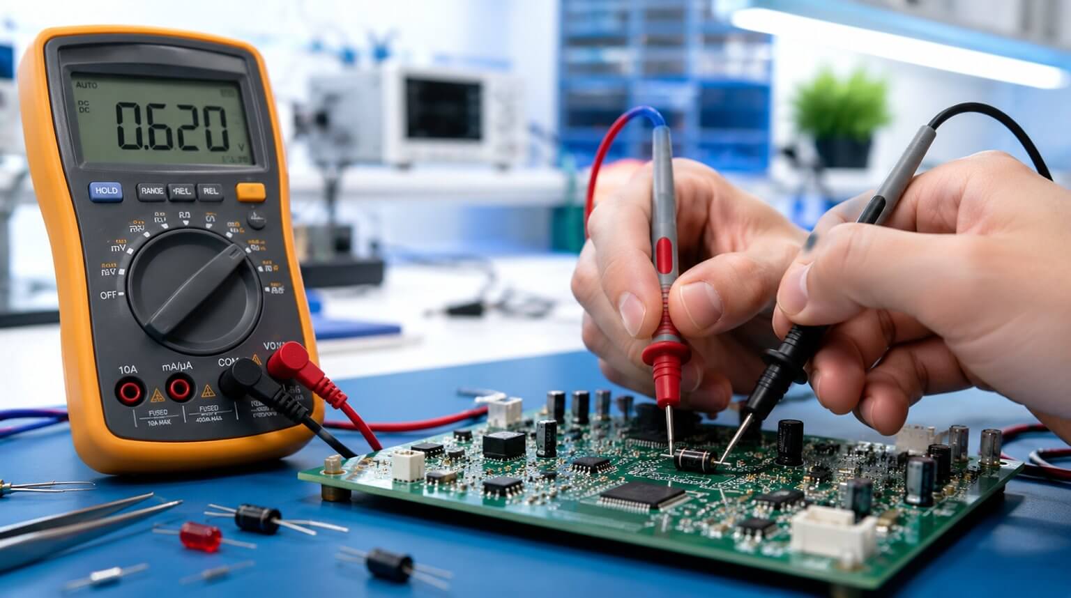
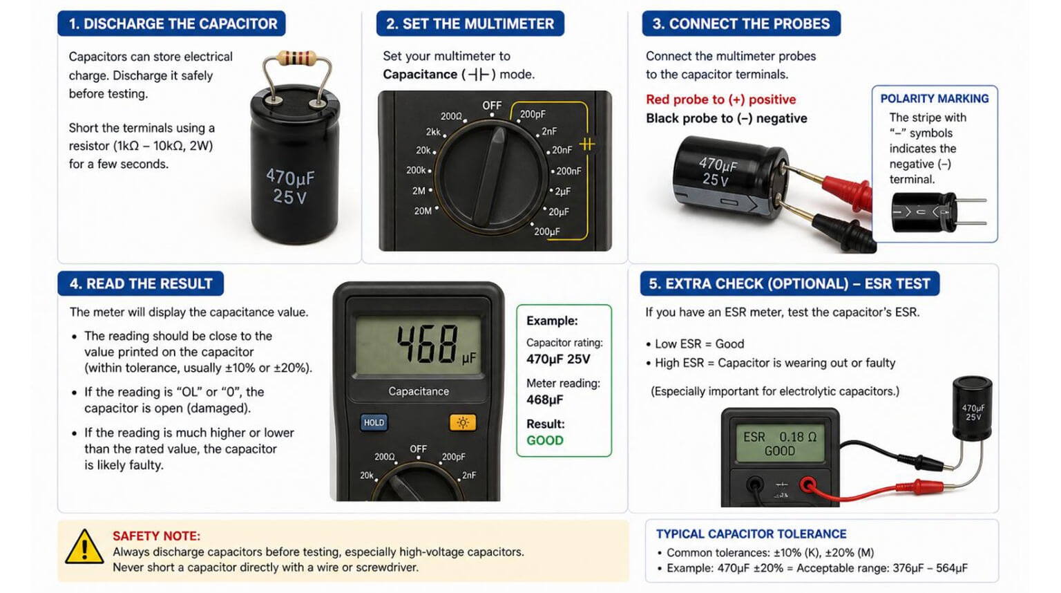
An LCR meter, which is a test instrument that measures a component’s inductance (L), capacitance (C), and resistance (R), can be used to verify values, check tolerances and diagnose component health. In this case you can use it to measure the actual capacitance value (pF, nF, µF).

You can also use an ESR meter, digital multimeter, oscilloscope, thermal camera and optionally an insulation/leakage tester to perform diagnosis and testing. The specific procedure is as follows:

  1. Do a Visual Inspection: Performing a simple visual inspection can help you identify a bad capacitor. Look for bulges, vents, leakage, discoloration, or cracked chips.
  2. Perform an ESR Check: Use an ESR meter; high ESR is a good indicator for failing electrolytic capacitors even in-circuit.
  3. Perform Capacitance Measurement: Use an LCR meter for measurements; for MLCC capacitors, measure under DC bias if DC operating voltage is significant.
  4. Do a Leakage Current Test: Measure DC leakage current at rated voltage (usually out-of-circuit or isolated) for electrolytics and film parts.
  5. Check Ripple Voltage in the Circuit: On power supplies, use an oscilloscope to view ripple voltage across the capacitor; excessive ripple indicates undersized or failing capacitors.
  6. Perform Thermal Inspection: You can use a thermal camera to find hot capacitors; this is a good sign of internal heating.
  7. Inspect for Mechanical Damage: For MLCCs, flex the board slightly (safely) to see if intermittent contacts or cracks occur; or inspect under magnification.
  8. Interpret the Results: A rising ESR above the manufacturer’s typical range or capacitance dropping more than 20% to 30% (depending on the tolerance and function) are common replacement thresholds.

How to Prevent Capacitor Failure

  • Derating

Employ voltage and temperature derating. For electrolytics and tantalum capacitors, select voltage ratings significantly higher than the operating voltage (1.5-2x for tantalum; at least 20-50% margin for electrolytics depending on application). For MLCCs, you can allow for DC-bias capacitance loss.

  • Temperature Rating

Choose capacitors with higher temperature ratings (for example, 105 °C vs. 85 °C) for long life in warm environments. The life of the capacitor roughly halves for each 10-20 °C increase in temperature, depending on the chemistry of the capacitor’s material.

  • ESR and ESR stability

For power supplies and low-impedance circuits, use low-ESR types or parallel capacitors to lower ESR. Keep an eye on the ESR rise with age.

  • Ripple Current Capability

Select low-ESR parts for the expected ripple current with margin.
Note that Polymer electrolytes and some electrolytic designs perform better in high ripple.

  • Mechanical Robustness

Make use of vibration-rated parts, anchor large cans, and design pads for proper mechanical stress relief.

Follow appropriate soldering profiles to avoid thermal shock.

  • PCB Layout and Cooling

Ensure that capacitors are kept away from heat sources.

Provide airflow and thermal dissipation, and avoid local hot spots.

  • Quality and Sourcing

When sourcing capacitors, use reputable manufacturers and verify parts against counterfeits. You can check datasheets for lifetime, ripple, ESR specifications, and key details.

  • Alternate Technologies

When longevity and reliability are critical for your application, consider film or solid polymer capacitors over wet electrolytes, if it is possible.

Replacement and Repair Best Practices

When to Redesign or Replace

If failures recur, reassess specification margins, layout, cooling, and whether a different dielectric type or topology is warranted.

If ESR is significantly above datasheet typical values, the capacitance has been reduced beyond tolerance for the application, there is visible damage or leakage, or there are circuit symptoms traceable to decoupling/filter degradation, then it is time to replace the capacitor.

Safety

When handling capacitors, safety is of utmost importance. Always discharge capacitors before handling them. Observe polarity and voltage ratings, use insulated tools and lastly follow ESD precautions.

Selecting Replacements

You can match or exceed capacitance, voltage rating, temperature rating, ripple rating, and ESR profiles for your replacement capacitor.

Choose higher temperature and low-ESR alternatives for long life.

Lastly, consider paralleling smaller capacitors to achieve lower ESR or better ripple handling.

Soldering

Keep factors to consider when soldering include:

  1. Applying appropriate reflow/rework profiles.
  2. Avoiding overheating the capacitor body.
  3. Allowing adequate cool down.
  4. For large radial cans, apply the correct soldering iron temperatures and times.

Final Thoughts

Capacitor failure is not only a component-level issue. In many cases, it is closely related to whether the capacitor was correctly selected, reliably sourced, and properly assembled for the real operating conditions of the product.

For PCBA projects, a capacitor with the right value on paper is not always enough. The supplier channel, component brand, voltage and ripple rating, soldering process, polarity control, and inspection quality can all affect long-term reliability.

PCBCool supports customers with electronic component sourcing and PCBA assembly. We can help source capacitors and other key components from preferred or customer-specified brands, and assemble PCBAs under controlled production and inspection processes to reduce avoidable reliability risks.

Frequently Asked Questions (FAQ)

Q1: Is AOI Inspection Performed on Every Board?

A: Not always. It depends on the manufacturer, the specific project, and customer requirements. For projects with higher reliability demands, such as medical and automotive electronics, AOI is typically performed on every board.

Q7: Can Customers Specify AOI Inspection Standards?

A: Yes. For projects with special quality requirements, PCBCool can follow customer-defined inspection priorities, acceptance criteria, tolerance ranges, or specific defect control requirements.

John
John | Electrical Systems and Industrial Automation Specialist

John is an experienced specialist in electrical systems, instrumentation, process automation, and industrial control. He has worked on equipment installation, maintenance, factory testing, and commissioning, giving him practical insight into how industrial systems perform in real operating environments.