Just like any other electronic component, capacitors may fail or degrade over time; this can affect circuit performance. That is why capacitor testing is a basic but important skill for troubleshooting electronic devices.
Capacitor testing can be described as the process of checking a capacitor’s ability to store and release electrical charge. This aids in establishing its overall health and in decision-making on whether it needs replacement.
We can’t underestimate the importance of ensuring safety first when handling capacitors. Always switch off the power and unplug devices before working on them. Discharge capacitors safely before performing any tests. Use insulated tools and eye protection when necessary.
In this article, we will cover basic features of capacitors, common failure modes, and show you practical, step-by-step tests you can perform on capacitors with common tools.
A capacitor is a device used to store electric charge in the form of an electric field. Its basic structure is simple: two conductive plates separated by a dielectric material. The plates may be made of metal foil or another conductive material, while the dielectric may be air, paper, plastic, ceramic, or another insulating material.
When a DC voltage V is applied across the leads of a capacitor, one of its plates charges to a value of +Q, while the other plate will charge up to –Q. Here, Q is the charge in coulombs, Q = CV, and C is the capacitance, or simply the proportional constant that relates Q and V.
The positive (+Q) and negative charges (-Q) build up on the plates, creating an electric field. The charge that is stored depends on the applied voltage, plate size and shape, and the dielectric type and thickness.
Capacitance is measured in farads, F (1 F = 1 C/1 V) and is equal to one coulomb of charge per volt. Typical capacitor values are in a range such as microfarads (µF) = 10-6 F, nanofarads (nF) = 10-9 F or picofarads (pF) = 10-12F units.
Capacitors come with various capacitance values, typically from 1 p (1 x 10-12F) to 68,000 µF or 0.068 F, and with various maximum voltage ratings, from a few volts to thousands of volts depending on the type of capacitor. In a nutshell, the capacitance simply tells us how much charge can be stored within the capacitor.
Capacitors are used as energy storage components to accumulate energy through long periods of time and discharge the energy over longer or shorter periods.
Typical applications for capacitors include:
- Resistive-capacitive coupling for audio and radio frequency.
- RF and intermediate frequency cathode bypass.
- Used as a DC-blocking or AC-coupling capacitor to block DC while allowing AC signal components to pass.
- Used as a decoupling capacitor – allows DC to continue along the path, while diverting high-frequency signal components to ground.
- Tuned circuits, filter networks, timing circuits, LC resonant circuits, RC snubber circuits, and so forth.
Before testing a capacitor, it helps to understand the main specifications that affect how the component performs in a circuit:
- Capacitance (C) – as we already mentioned, this is the stored charge per volt.
- Voltage rating (V) – this is the maximum safe DC voltage.
- Tolerance – the acceptable deviation from the nominal value.
- Equivalent Series Resistance (ESR) – this is the internal resistance affecting AC/ripple performance.
- Equivalent series inductance (ESL) – the inductance of the capacitor’s leads in series with the equivalent capacitance of the capacitor plates.
- Leakage current– DC current that flows through the dielectric.
- Polarity – electrolytic and tantalum capacitors are polarized.
A capacitor may go bad due to many factors, but in most cases failure in capacitors arises when there is one or more of the following:
- Short circuit
- Open circuit i.e., no capacitance
- Increased ESR (reduced filtering/ripple suppression)
- Reduced capacitance
- Excessive leakage
- Physical signs – bulging, venting, electrolyte leakage
There are several tools and equipment you need when performing a test on a capacitor, some of them include:
- Digital multimeter (with capacitance function if available).
- LCR meter (used to verify values, check tolerances, and diagnose component health).
- ESR meter (handheld recommended for in-circuit ESR checks).
- Dedicated capacitor tester (optional).
- Oscilloscope (for dynamic/in-circuit waveform checks.
- Resistors for safe discharge (10 kΩ – 100 kΩ depending on capacitance/voltage).
- Insulated screwdriver or discharge probe (use only as last resort).
- Soldering iron and de-soldering tools (for out-of-circuit tests).
- Safety gear: gloves, eye protection.
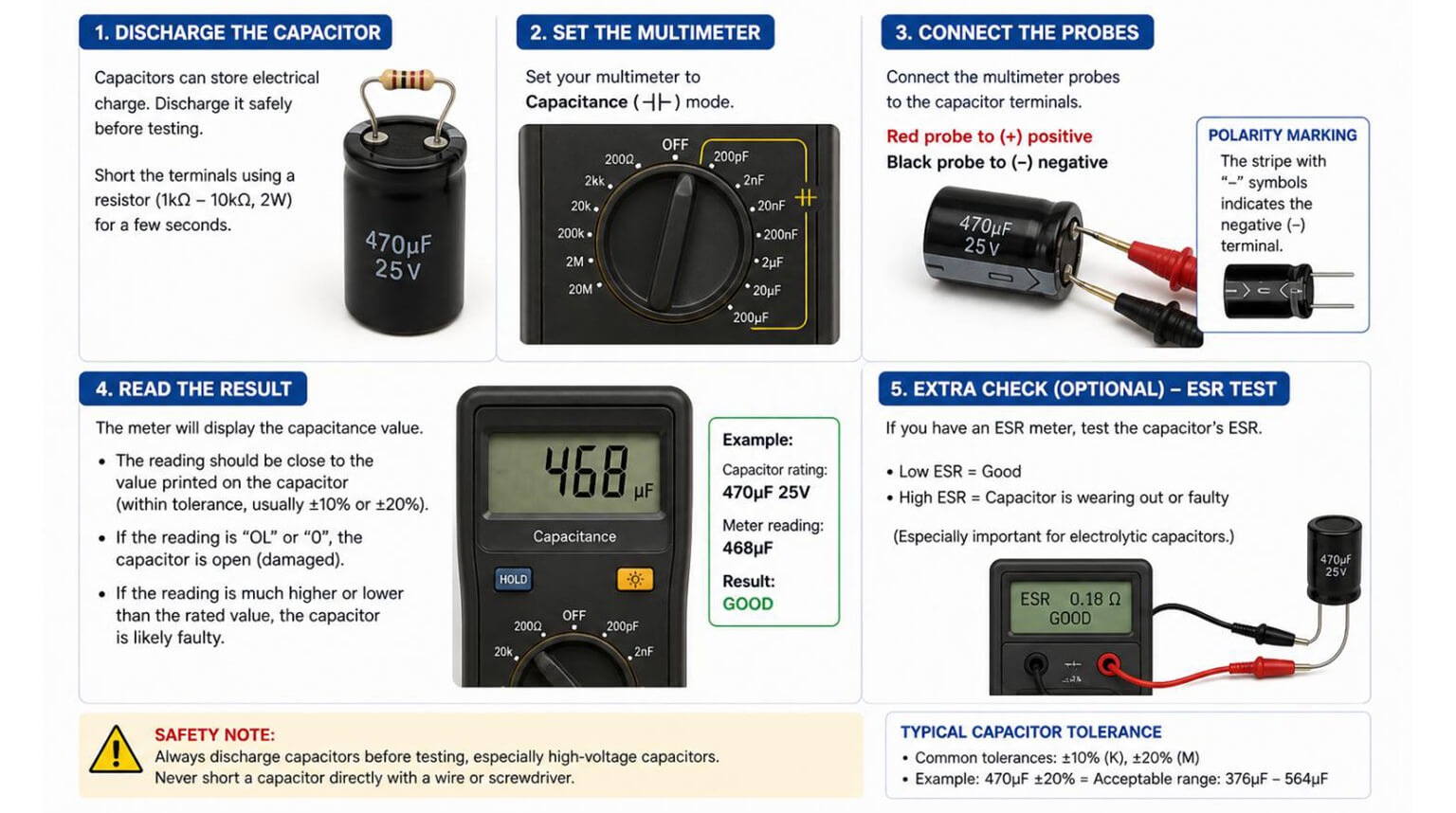
A charged capacitor can hold hazardous voltage even when the device is off. Therefore, it is important to always discharge the capacitor before embarking on any tests.
To discharge a capacitor, do the following:
- Turn off the power to the circuit and unplug the device.
- Use an insulated screwdriver or resistor’s lead to short the capacitor terminals briefly, releasing the stored energy. Connect a resistor across the terminals with insulated leads until the voltage reads near zero. Use one rated for the expected power and for safety.
- In case of high-voltage capacitors such as microwave or motor start capacitors, use a discharge tool with a resistor to prevent sparks.
- Verify discharge with a voltmeter.
- Visually inspect the capacitor for bulging, leaking electrolyte, corrosion, discolored/burnt areas, cracked casing, or missing vent slits.
- Check polarity markings, and ensure electrolytic capacitors are installed correctly.
- Inspect solder joints for cracks or cold joints.
- If you see obvious physical damage, plan to replace the capacitor regardless of meter readings.
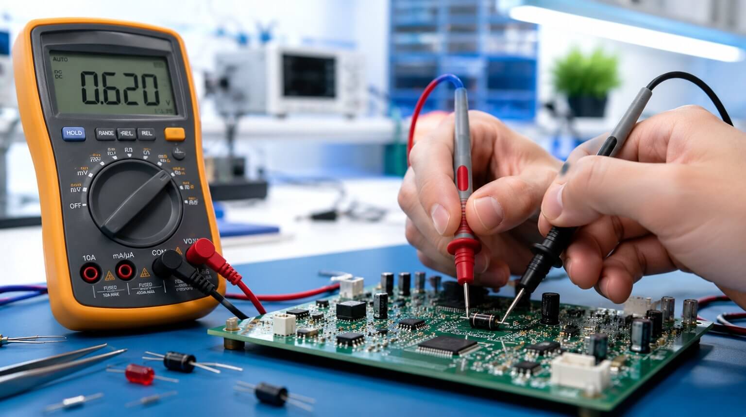
Measuring capacitance with a digital multimeter is one of the most common ways to check whether a capacitor is still within its rated value. Follow the steps below:
- Ensure the power is disconnected.
- Isolate the capacitor and discharge (as explained above). Before conducting any test, ensure that the capacitor is not connected to any power source or other components within a circuit and it is discharged.
- Set the multimeter to capacitance mode (if available); if not, set the highest resistance range to detect shorts or opens (We have covered this in the next section).
- Connect the probes to the capacitor terminals/leads. Connect the positive (red) multimeter lead to the positive (longer) terminal of the capacitor and the negative (black) lead to the negative (shorter) terminal of the capacitor.
- The reading should be within 10% of the capacitance rating printed on the side of the capacitor. A significantly lower reading or unstable value indicates a failing capacitor.
Note that modern digital multimeters have a dedicated symbol for capacitance testing, normally represented by:
- Two parallel lines: representing a capacitor’s internal plates, often marked as ‘II’ or with a small ‘+’ sign for polarity.
- µF icon: that indicates that the meter is in capacitance mode, ready to measure microfarads.
- Diode symbol with “C”: You may find some meters that combine this with continuity or diode mode, allowing basic checks.
When you select the capacitance testing mode, the multimeter usually sends a small current through the capacitor and measures its charge and discharge rate to calculate the capacitance. It is important to always remember to discharge the capacitor before switching to this mode to avoid damaging the multimeter.
The capacitance setting may not be available on your multimeter; in that case, you can test the capacitor by measuring resistance. In resistance mode, a multimeter can check a capacitor’s basic charging and discharging behavior.
To conduct this test following the following steps:
- Ensure you have switched off the power.
- Disconnect the capacitor from the circuit.
- Discharge the capacitor by shorting the terminals using a screwdriver, a resistor or a jumper wire.
- Set the multimeter to the Ω (ohm) range.
- Connect the probes to the capacitor terminals. Connect the (red) multimeter lead to the positive (longer) terminal of the capacitor and the negative (black) lead to the negative (shorter) terminal of the capacitor.
- Check the readings on the multimeter. A capacitor that is in a good working condition should show low resistance initially, and then slowly increase toward infinity as it charges. This means that the capacitor is charging and discharging normally.
- A reading of zero (shorted) or constant infinity (open), this implies that the capacitor is failing or bad.
What about if you don’t have a multimeter, but you want to know the state of a capacitor? No need to worry, you can perform a simple test to check the basic functionality of the capacitor using simple items:
- Find a small DC power source (1.5 – 9 V) and a low-voltage light bulb or LED to use for this test.
- Connect the capacitor to the power source for a few seconds, and then disconnect it.
- For a short time, touch the capacitor terminals to the bulb or LED. If it flashes, the capacitor is holding a charge. If there is no flash, it may be failing or open-circuited.
Though not precise, this simple technique can be of great help especially in emergencies in detecting dead capacitors.
ESR is very critical for power supply and filter capacitors. As a technique of testing capacitors, do the following:
- Use a handheld ESR meter. ESR meters usually inject a small AC signal and measure impedance at low frequency.
- Test in-circuit first – ESR meters most often than not work in-circuit for electrolytic capacitors because other circuit impedances usually appear inductive or resistive differently than ESR. If the results seem suspicious, remove the capacitor for an accurate ESR reading.
- Compare ESR readings to expected ranges; there is no universal table to check with, but typically ESR increases with capacitance and age. Very high ESR indicates a failing capacitor even if the capacitance appears acceptable.
This technique for testing capacitors is helpful for power supplies and audio circuits. Follow the following steps to perform the test:
- With the circuit powered and probes connected properly, observe waveforms accurately, observe the waveforms across the capacitor or its node.
- Look for excessive ripple on power rails, slow charge/discharge behavior, or abnormal transient responses.
- For decoupling capacitors, inject a square-wave or step and observe the RC charging curve for anomalies.
- A capacitor with high ESR will show large ripple and slow transient suppression.
If any of the following situations occur during the testing process, it indicates that you may need to replace the capacitor:
- There is visible physical damage, i.e., you can see bulging, leaking, burnt casing, discolored areas, etc.
- Zero or infinite reading on the resistance test.
- ESR is significantly above expected values for that type/capacitance (high ESR causes heating and poor filtering).
- Capacitance measured is 20-30% lower than its rated value (Capacitance is outside tolerance by a substantial margin).
- Leakage or abnormal continuity reading is detected.
- The capacitor is shorted or open.
Note that in-circuit readings can be influenced by parallel components; if uncertain de-solder one lead and conduct the test out of the circuit.
Best Practices for Capacitor Replacement
Consider keeping the following best practices when replacing capacitors:
- Match or exceed original specifications: capacitance, voltage rating (choose equal or higher), temperature rating e.g., 105 °C for higher reliability.
- Observe polarity when installing polarized capacitors.
- Use proper soldering techniques – minimal heat exposure and avoid prolonged heating.
- Physically secure larger capacitors to prevent mechanical stress.
- For electrolytics in power supplies, select low-ESR, high-temperature types.
Testing a capacitor is a practical way to diagnose circuit problems, prevent unexpected failures, and improve repair decisions. Whether you are using a digital multimeter, ESR meter, LCR meter, or oscilloscope, the goal is the same: to understand whether the capacitor can still perform reliably in the circuit.
But capacitor reliability does not depend on testing alone. It also depends on choosing the right replacement part, sourcing components from reliable channels, and assembling the board under a controlled manufacturing process. A capacitor with the wrong voltage rating, poor ESR performance, unsuitable temperature rating, or inconsistent quality can create new reliability problems even after the original fault has been repaired.
For companies building electronic products, this is where a turnkey EMS manufacturing partner can make a real difference. PCBCool provides PCB fabrication, component procurement, PCB assembly, box build, functional testing, and final product delivery. We help customers manage both the manufacturing process and the component supply chain, so the finished PCBA is not only assembled correctly but also built with properly sourced and qualified parts.