Resistors are an essential part of almost every electrical circuit, but they are often presented too simply to fully explain how they work and why they are needed. This article discusses the basic principles of resistance, how resistors operate within electrical circuits, and how they relate to voltage and current.
A clear understanding of resistors is useful for designing circuits, diagnosing circuit problems, and selecting the right component for a specific application.
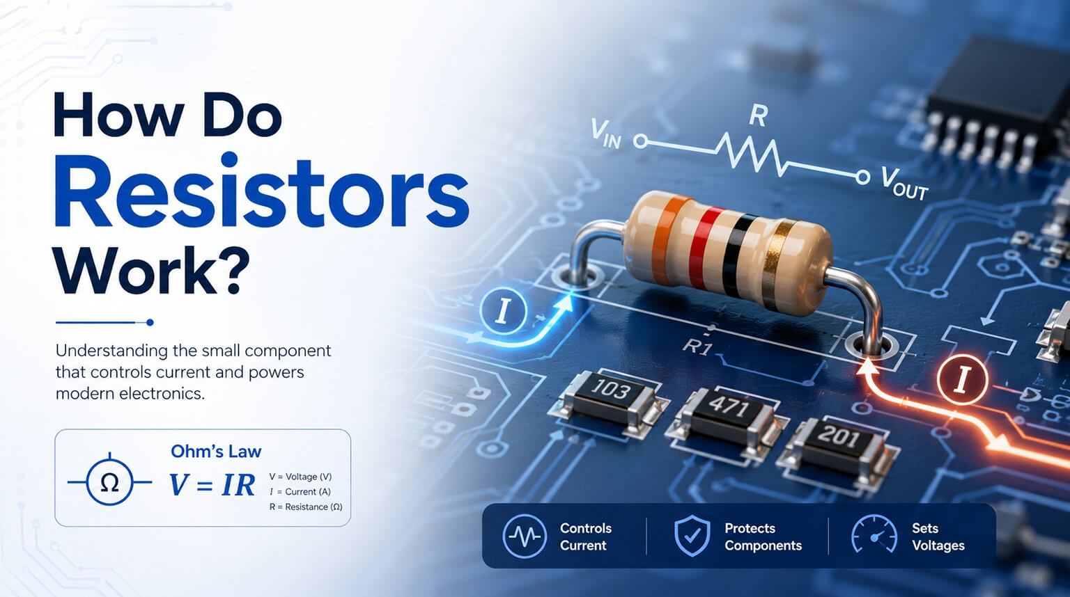
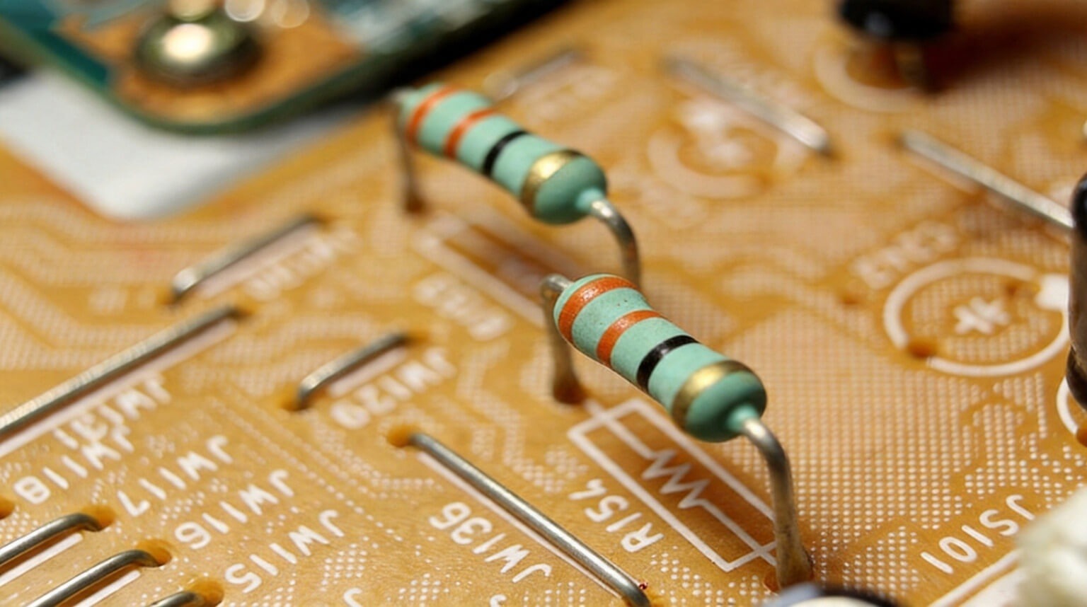
A resistor is a passive electronic component that resists electrical current flowing through a circuit. In many circuit diagrams, the resistor symbol is shown as a zigzag line, which makes resistors easy to identify.
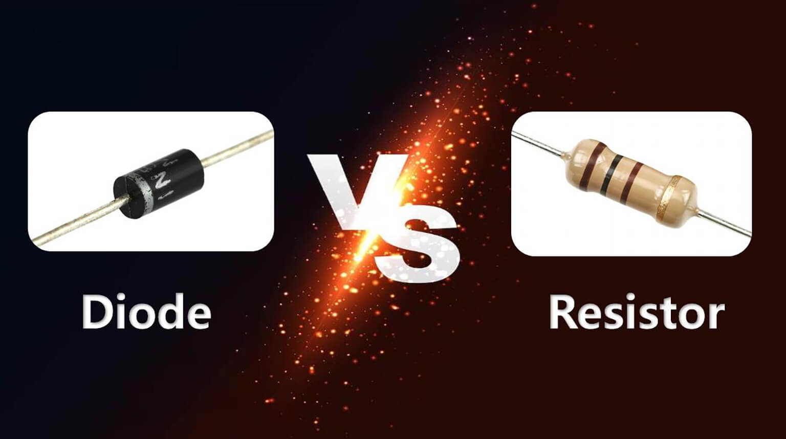
Several types of resistors exist, but the most common through-hole type is cylindrical, with colored bands that indicate resistance value and tolerance. Surface-mount resistors often use numbers instead. These markings allow engineers to identify resistor values quickly without doing complex calculations.
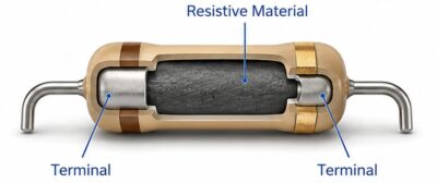
A resistor is made up of a resistive material, such as carbon film, metal film, or a wire-wound coil, with two terminals connected through that material. When electric current passes through the resistive material, it encounters resistance, and some electrical energy is dissipated as heat.
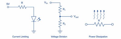
A resistor in an electrical circuit has three fundamental functions:
- Current limiting: It limits current flow to protect components from damage caused by excessive current.
- Voltage division: It helps provide required voltage levels at different points in a circuit.
- Power dissipation: It dissipates electrical energy as heat, allowing unused energy to be managed safely.
In real circuits, these functions are often used together. A resistor may protect a component, set a reference voltage, control a signal level, or help keep a circuit operating within a safe range.
Without resistors, many electronic circuits would fail shortly after being turned on because semiconductor components could receive excessive current or voltages beyond their ratings. Most circuits would also lose the ability to properly control signal levels.
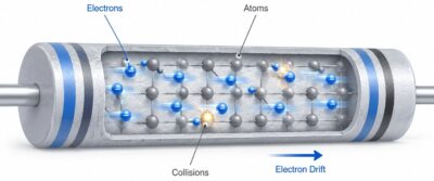
Electrical resistance results from the interaction between moving electrons and the atomic structure of the resistor’s material. When a voltage is applied across a resistor, an electric field causes electrons to drift through the resistive material.
As the electrons move, they repeatedly collide with atoms in the material. These collisions slow the movement of electrons and scatter their direction of travel. Because the electrons cannot move freely through the material, the resistor opposes current flow. This opposition to electron movement is what creates electrical resistance.
The resistance of a resistor depends mainly on three factors: the material used, the length of the resistive element, and its cross-sectional area.
One of the most important equations in electronics is Ohm’s Law, which describes the relationship between voltage, current, and resistance. It is commonly written as:
V = IR
where:
- V = voltage, measured in volts (V)
- I = current, measured in amperes (A)
- R = resistance, measured in ohms (Ω)
The formula can also be rearranged as I = V / R, which means that current is directly proportional to the applied voltage and inversely proportional to resistance.
For example, if a 1000-ohm resistor is connected to a 10-volt power supply, 10 mA will flow through the resistor. This can be calculated using Ohm’s Law: I = 10V / 1000Ω = 0.01A, or 10 mA.
If the 1000-ohm resistor is replaced with a 2000-ohm resistor while the voltage remains 10 volts, the current decreases to 5 mA. Conversely, if the voltage is increased to 20 volts while the resistance remains 1000 ohms, the current increases to 20 mA.
By using an appropriately rated resistor, designers can ensure that the current flowing through a circuit component does not exceed its maximum rated value.
When using Ohm’s Law in a real-world circuit, it is important to understand how the components are connected. In a series connection, components are wired in line, and the same current flows through each component. In a parallel connection, components are connected across the same voltage, but the current divides between the different branches.
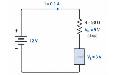
In a basic series circuit consisting of a power supply, a resistor, and a load, the total supply voltage is divided between the resistor and the load. For example, if a 12-volt power supply is connected through a resistor to a 3-volt load, the resistor must drop the remaining 9 volts. According to Ohm’s Law, if the desired current is 100 milliamps, the required resistance is:
R = 9V / 0.1A = 90 ohms
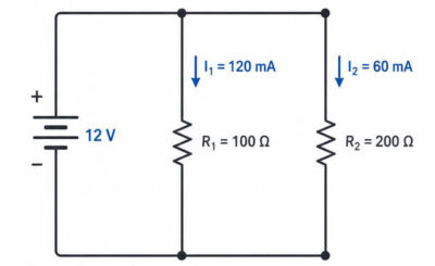
In a parallel circuit, the same voltage appears across each branch. For example, if a 12-volt power supply is connected across a 100-ohm resistor and a 200-ohm resistor in parallel, both resistors have 12 volts across them. The 100-ohm resistor draws 120 milliamps, while the 200-ohm resistor draws 60 milliamps, giving a total current of 180 milliamps.
Heat generated in a resistor is a direct result of electrical resistance. As electrons pass through the resistive material, they collide with atoms in the material. Energy from the moving electrons is transferred to the atoms, causing them to vibrate more intensely. This increased atomic vibration appears as heat.
The heat generated in a resistor is measured as power dissipated, in watts. The amount of power dissipated through a resistor can be calculated using the formula:
P = I²R
where:
- P = power, measured in watts (W)
- I = current, measured in amperes (A)
- R = resistance, measured in ohms (Ω)
Another way to calculate power in a resistor is to use:
P = VI
where V is the voltage across the resistor and I is the current through the resistor.
For example, a resistor carrying 1 ampere of current with a resistance of 10 ohms will dissipate 10 watts of heat.
Resistors are commonly used to limit the amount of current flowing through devices such as LEDs. An LED connected directly to a 5V power supply would draw too much current and could burn out quickly. If a resistor is added in series with the LED, it limits the current so the LED can operate safely.
For example, a typical red LED may require about 20 mA at 2V. If it is connected to a 5V power supply, the resistor must drop the remaining 3V. Using Ohm’s Law, the required resistance is:
R = 3V / 0.02A = 150 ohms
Furthermore, many analog circuits and sensors operate at voltages lower than the main power supply voltage. A voltage divider uses two resistors in series to reduce an applied voltage. For example, if a 10V supply must provide 5V to a sensor input, two equal resistors, such as two 10 kΩ resistors, can be used to produce 5V at the junction between them.
Resistors are also used for impedance matching and signal conditioning by controlling how signals propagate through a circuit. In audio circuits, for example, resistors can help set input impedance and protect amplifiers from excessive signal levels.
Biasing resistors are used to set the operating point of transistors and other active devices. In analog circuits, they help establish the correct DC operating point so the circuit can respond properly to an input signal.
Pull-up and pull-down resistors establish a known voltage level on signal lines when no active device is driving them. This helps digital logic circuits avoid floating inputs and produce predictable responses.
When learning about electronics, you will notice that carbon film resistors are among the most frequently used and economical types of resistors. They are made by placing a layer of carbon on a ceramic rod and then attaching metal lead wires to either end. Typical tolerances for carbon film resistors are between 5% and 10%, which means the measured resistance value can vary from the stated value by that percentage.
Metal film resistors have a much greater degree of accuracy and stability compared with carbon film resistors. The resistance element is created by depositing a very thin layer of special metal alloy onto a ceramic core. Metal film resistors are usually more expensive than carbon film resistors, but they are useful in circuits where accurate and stable resistance values are important.
Wirewound resistors, as the name suggests, consist of a resistive wire wound around a ceramic or fiberglass cylinder. The wire is usually made from a high-resistance alloy such as nichrome. These resistors can handle high power levels, making them suitable for high-current and power supply applications. However, because the wire is wound around a core, wirewound resistors can have some inductance, especially at higher frequencies.
Thick film and thin film resistors are produced by depositing a layer of resistive material onto a ceramic substrate. They are commonly used in surface-mount applications because they can be made very small while still providing good temperature stability, accuracy, and reliability.
While resistors are often thought of as simple components, their role in electronic circuits is essential. They help control current, divide voltage, stabilize signals, and protect other components from operating outside safe limits.
Understanding how resistors oppose current flow, how voltage and current relate through Ohm’s Law, and how resistors dissipate energy as heat provides a strong foundation for analyzing and designing circuits.
In PCB and PCBA projects, selecting the right resistor is not only about resistance value. Package size, tolerance, power rating, temperature coefficient, availability, and approved manufacturer requirements can all affect circuit performance and production stability. PCBCool can support component sourcing based on customer-specified brands or approved alternatives, helping customers reduce BOM risks during PCB fabrication and assembly.