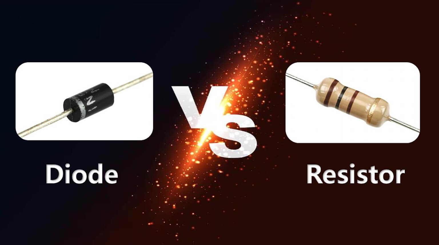
Both diodes and resistors are fundamental electrical components used in almost every electronic circuit. Although both affect current flow, they do so in very different ways.
In this article, we will explain the differences between these two key components in terms of electrical behavior, construction, and selection considerations in electronic design.
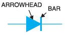
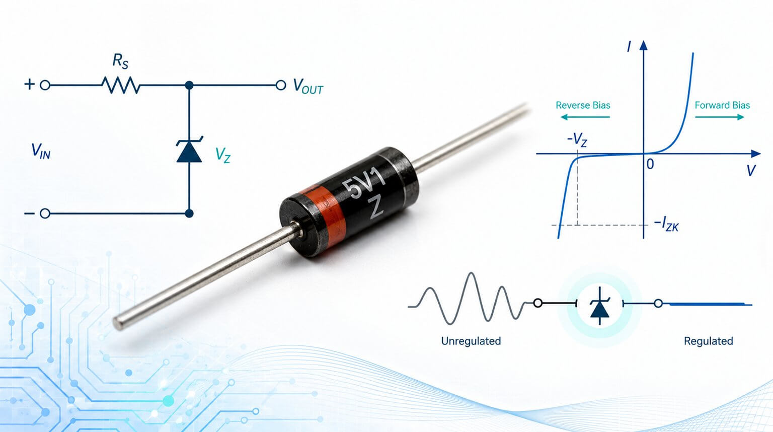
A diode is a semiconductor device formed by a p-n junction that conducts current mainly in one direction. It has two terminals: an anode and a cathode. A p-n junction diode is usually represented by the schematic symbol shown in the figure below:
The symbol indicates the direction of conventional current flow. When a p-n junction diode is connected in a circuit, its behavior depends on whether it is forward-biased or reverse-biased.
When the anode is positive with respect to the cathode, the diode is forward-biased and can conduct current. When the cathode is positive with respect to the anode, the diode is reverse-biased and usually blocks current, except for a small leakage current.
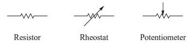
A resistor is a passive two-terminal component that opposes electrical current. It converts electrical energy into heat according to Ohm’s law:
V = IR
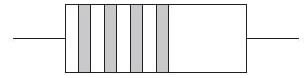
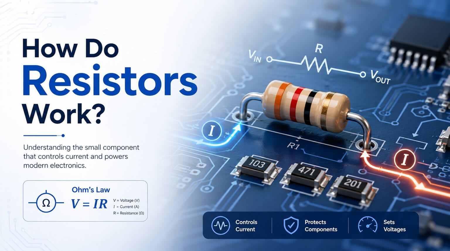
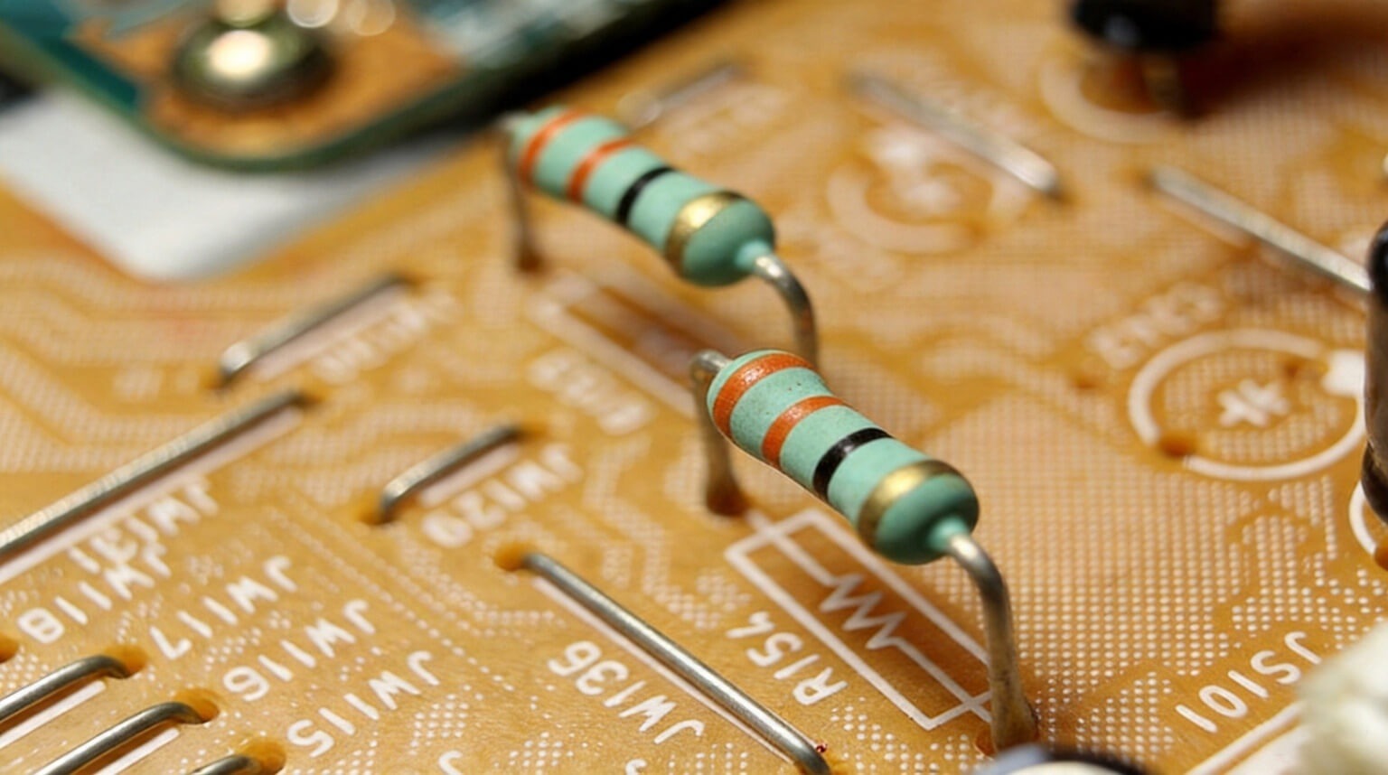
Low-power resistors commonly used in circuits are often marked with color-coded bands. These bands indicate the resistance value and tolerance, which describes the uncertainty in the resistance value.
The bands are usually grouped toward one end of the resistor. The band closest to the end is read as the first digit, the next band is the second digit, the next band is the multiplier, and the final band is the tolerance.
Standard Color Scheme for Resistors
For example, a resistor with the color code red, violet, orange, and gold has a value of 27 × 10³ Ω with a tolerance of ±5%.
A diode is polarized, and its orientation in the circuit determines whether it conducts under a given bias condition. Reversing a diode usually blocks current until breakdown occurs.
In a reverse-biased p-n junction diode, the depletion region expands and prevents normal current flow. In practice, a very small leakage current can still pass through the diode, but it is often small enough to ignore in many circuits. If the reverse voltage becomes too high, the diode may enter breakdown, which can be destructive unless the diode is designed for that purpose.
A diode’s maximum reverse-bias voltage rating is called the Peak Inverse Voltage, or PIV. This value is usually provided in the manufacturer’s datasheet.
A resistor is non-polar. It behaves the same way regardless of its orientation in the circuit.
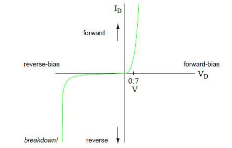
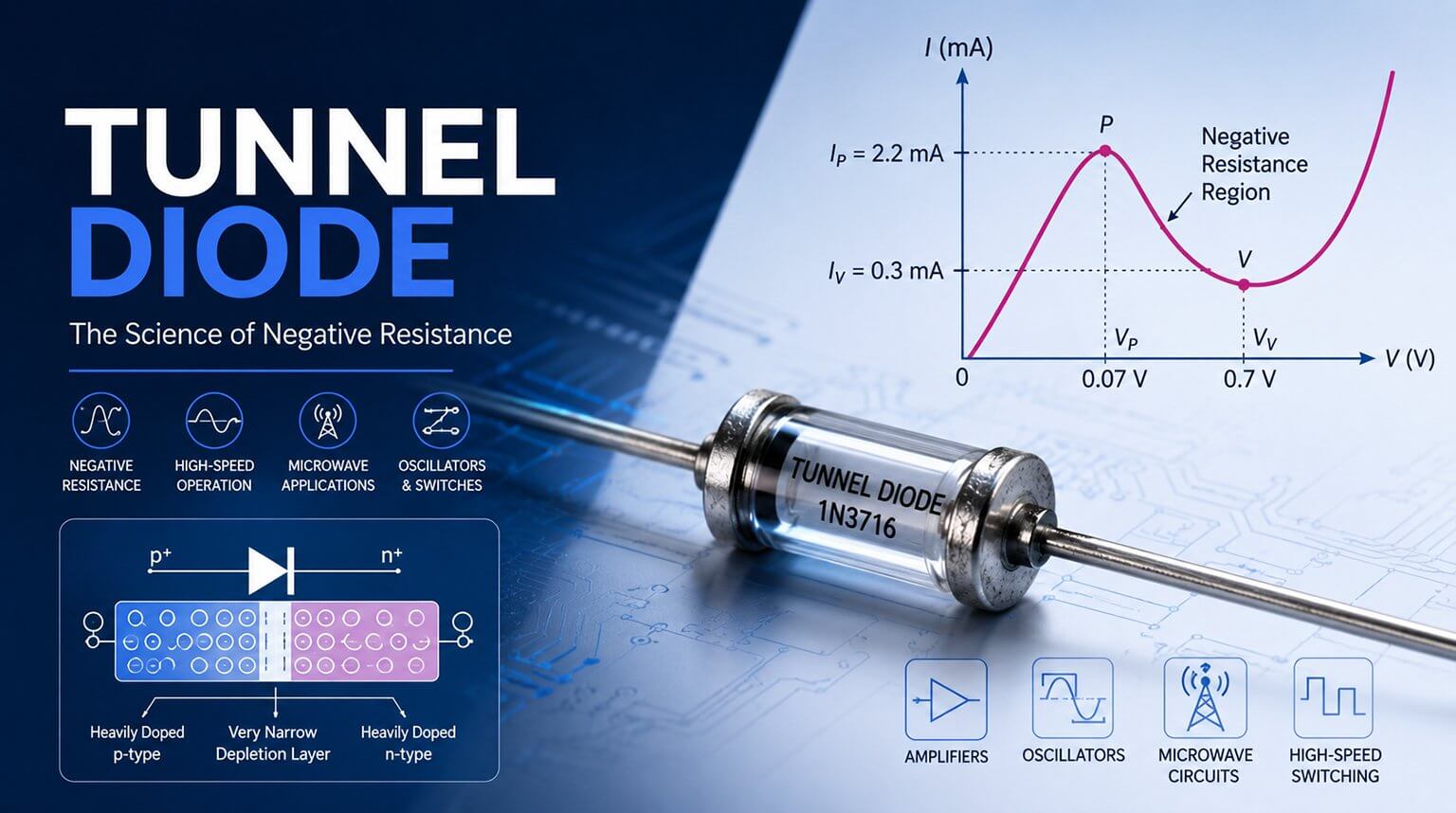
Diodes exhibit nonlinear behavior. In forward bias, a silicon diode typically begins to conduct significantly after its forward voltage reaches about 0.7 V. After this point, current rises rapidly. In reverse bias, the diode allows only very low current until breakdown occurs.
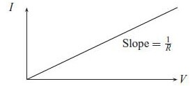
A resistor has a simple linear I-V characteristic. This linear relationship is expressed by Ohm’s law:
V = IR
The constant R is the resistance of the device. It is equal to one over the slope of the I-V characteristic, where slope = 1/R. The unit of resistance is the ohm, abbreviated as Ω. Any device with a linear I-V characteristic can be treated as a resistor.
The resistance of a device depends on its physical properties, including material, length, and cross-sectional area:
R = ρL/A
Where ρ is resistivity, L is length, and A is the cross-sectional area of the material.
Resistivity of Common Electronic Materials
| Material | ρ (10⁻⁸ Ω·m) |
|---|
| Silver | 1.6 |
| Copper | 1.7 |
| Nichrome | 100 |
| Carbon | 3500 |
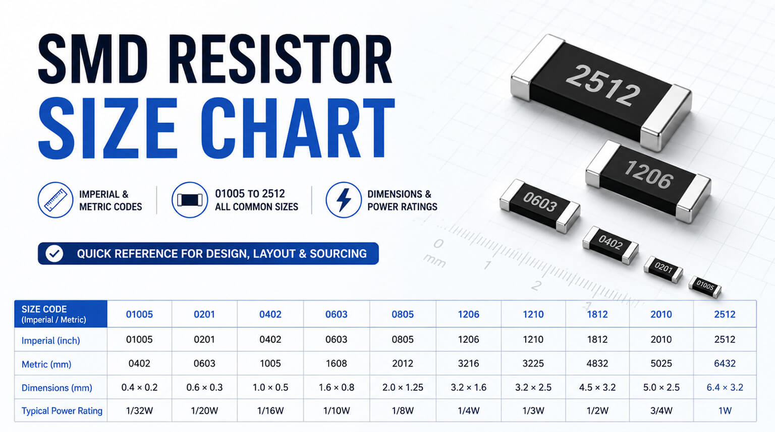
Interconnecting wires and PCB traces are typically made of copper or other low-resistivity materials, so their resistance can often be ignored in basic circuit analysis. When resistance is needed in a circuit, a discrete resistor made from a higher-resistivity material such as carbon or metal film is used. These resistors are available in many resistance values and power ratings.
The forward voltage drop of a semiconductor diode typically decreases as temperature increases. For silicon diodes, this change is often about -2 mV/°C. Reverse leakage current also increases with temperature. In some biasing conditions, this can contribute to thermal runaway.
Resistors have a temperature coefficient of resistance, usually called TCR or TC. It is commonly specified in parts per million per degree Celsius, or ppm/°C, relative to a nominal temperature such as 25°C.
For example, a resistor with a TC of 100 ppm/°C changes by about 0.1% over a 10°C change and about 1% over a 100°C change, assuming the temperature remains within the resistor’s rated operating range.
A positive TC means the resistance increases as temperature rises. A negative TC means the resistance decreases as temperature rises.
TC is important in applications where resistance must remain stable over temperature. It can also be useful in circuits that require temperature compensation.
Precision resistors usually have low TCR. Lower-cost resistor types may drift more with temperature. If a resistor is operated beyond its power rating, it may change value permanently or fail open.
Diode power dissipation in forward conduction is commonly estimated by multiplying the diode current by the forward voltage drop:
P = I × VF
In reverse bias, leakage-related power can be estimated as:
P = VR × IR
For resistors, power dissipation is given by:
P = I²R = V²/R
Resistors are rated by power, such as 1/4 W, 1/2 W, 1 W, or several watts. Proper derating and thermal management are important to avoid overheating, especially in power circuits.
Diodes have junction capacitance, which is related to the depletion region inside the p-n junction. This capacitance is usually small and is commonly measured in picofarads. It also changes with reverse bias.
Diodes also have reverse-recovery time, often written as trr. This is the time a diode takes to stop conducting after forward bias is removed.
Both junction capacitance and reverse-recovery time matter in high-frequency and switching applications.
Schottky diodes are often chosen when a circuit needs fast switching and a lower forward voltage drop. They are commonly used in low-voltage switching regulators, protection circuits, and high-speed applications. However, their reverse voltage rating, forward current rating, and leakage current must still be checked carefully against the circuit requirements.
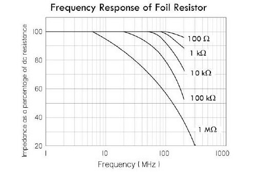
Ideal resistors are frequency-independent, but practical resistors have small parasitic inductance and capacitance. These parasitic effects can influence performance at very high frequencies or in fast pulse circuits, especially with wire-wound resistors.
For most low- and mid-frequency circuits, resistors behave close to ideal linear elements. At higher frequencies, however, the physical structure of the resistor and its leads can change the effective impedance. In RF, precision, or pulse applications, resistor type and package selection may therefore become important.
Diodes and resistors are both fundamental components, but they solve different circuit problems. A resistor provides controlled resistance to current flow, while a diode provides polarity-dependent control of current direction.
In practice, the two components are often used together. A resistor may limit current into a diode or LED, while a diode may guide current, protect a circuit, or shape a signal. Once you understand these basic differences, reading schematics and troubleshooting electronic circuits becomes much easier.