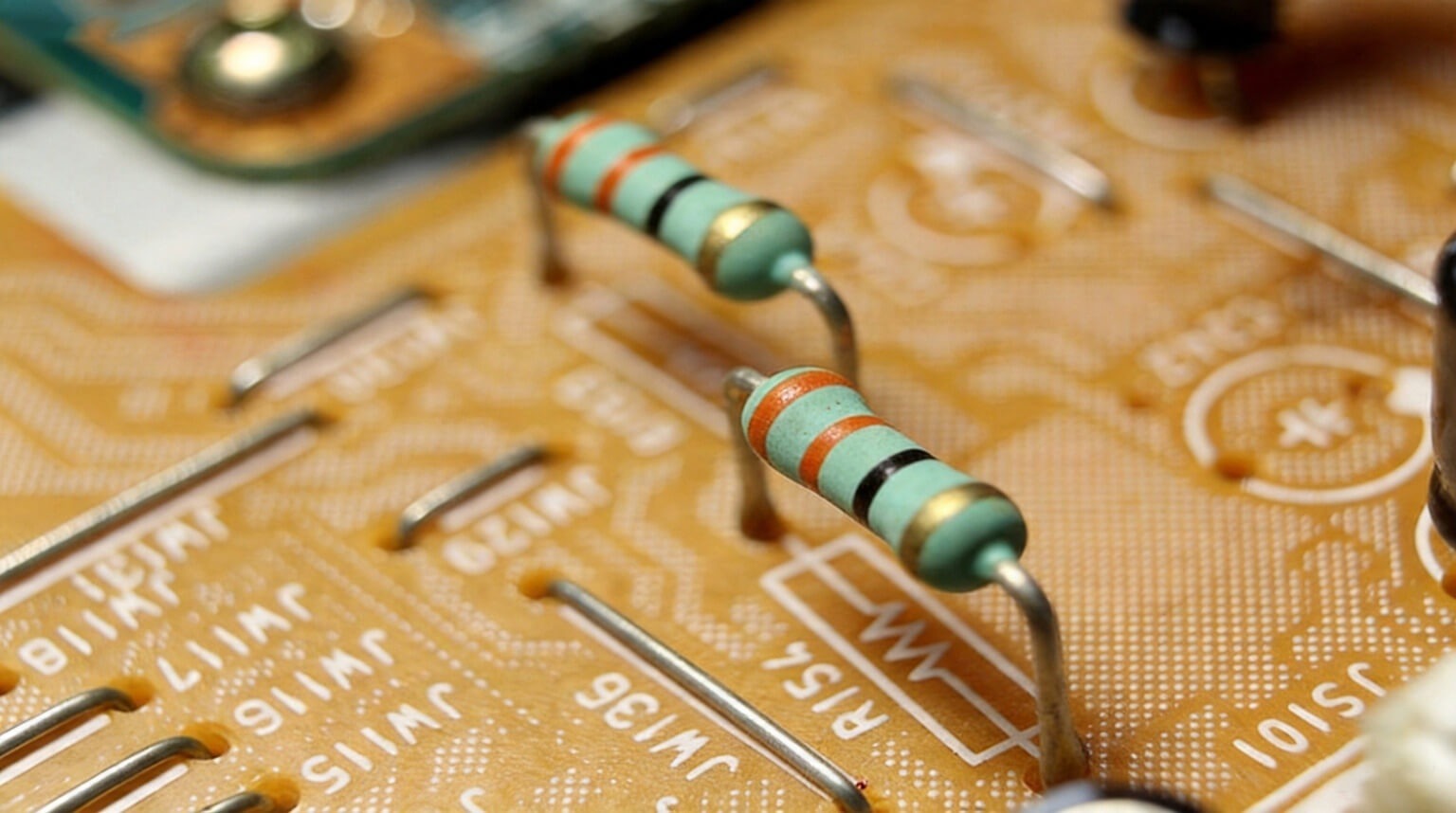
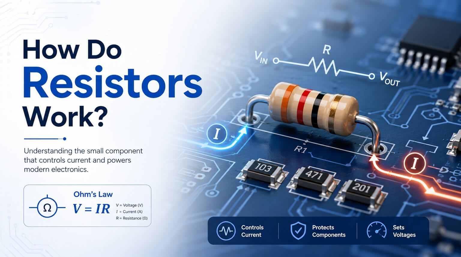
Resistors are among the most common components in electronic circuits, but they are often overlooked during troubleshooting. A resistor that appears fine in a schematic or simulation may perform differently in real-world conditions due to heat, humidity, aging, or electrical stress.
Knowing how to test a resistor is a basic but essential skill for engineers, technicians, and electronics professionals. Whether you are developing a product, diagnosing a circuit problem, or performing production checks, accurate testing helps prevent misdiagnosis and unnecessary component replacement.
This guide explains how to test a resistor using both basic and more advanced methods. In addition to standard resistance measurements, it also covers real-world factors that can affect performance, helping you make more accurate decisions in practical applications.
Before testing a resistor, it helps to understand what kind of problem you are trying to find. Different failure modes require different test methods, and using the wrong approach can easily lead to incorrect conclusions.
There are four common issues worth checking for.
- The first is resistance drift. This happens when the resistor’s actual value moves outside the tolerance range specified in the datasheet.
- The second is an intermittent open or short. This usually points to physical damage, cracking, weak internal connections, or unstable contact within the resistor body or its terminations.
- The third is the voltage coefficient of resistance (VCR). In this case, the resistance changes slightly as the applied voltage changes. This effect is especially important in precision and analog circuits.
- The fourth is temperature-related resistance change. A resistor’s value naturally shifts with temperature, but excessive change may indicate an unsuitable temperature coefficient, poor part selection, or an underlying reliability problem.
Each of these conditions requires a different testing method. If they are treated as the same problem, a resistor may appear normal in a basic measurement while the real fault goes undetected.
For many standard resistor checks, this method is simple, fast, and accurate enough for practical use.
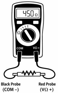
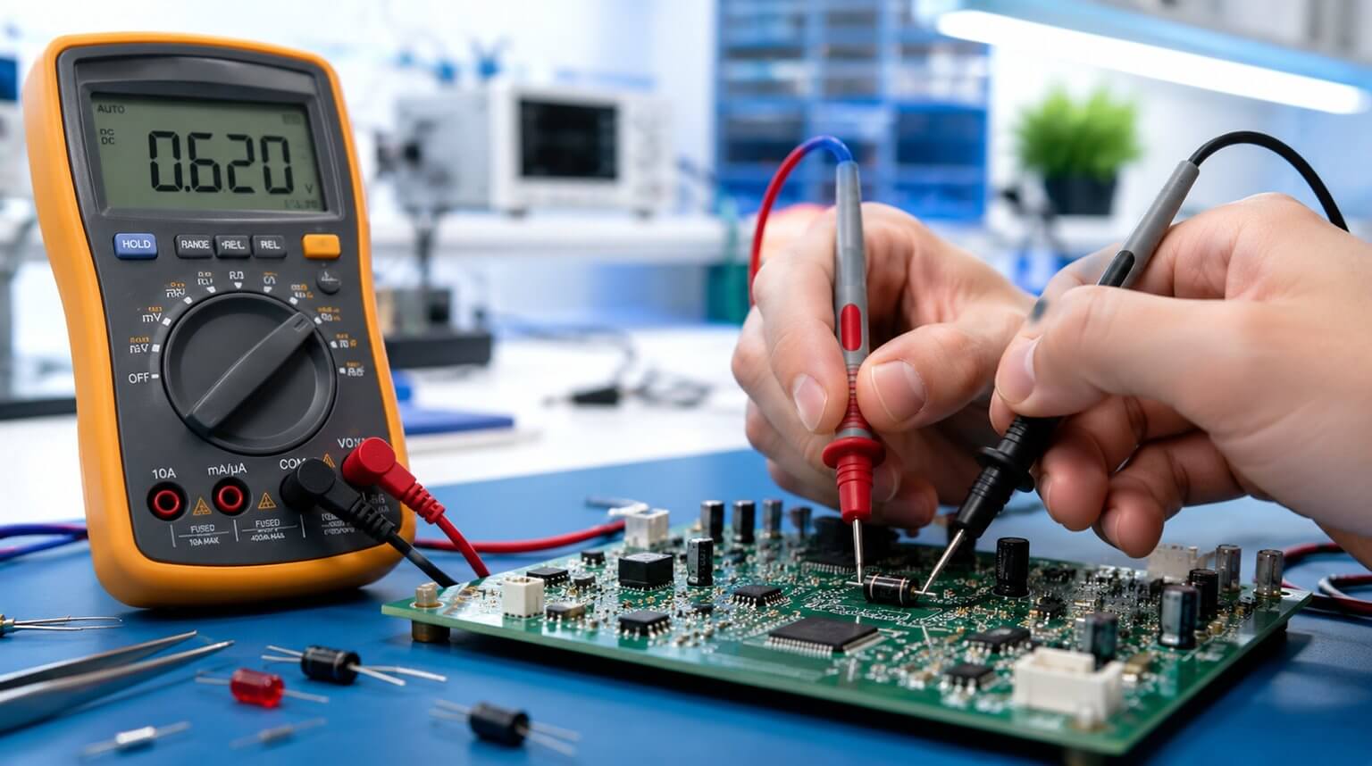
In a basic resistance measurement, the meter applies a small test current and measures the resulting voltage drop across the resistor. It then calculates the resistance using Ohm’s law. For most resistors with values above about 100 ohms, a standard two-wire measurement is usually sufficient.
However, low-resistance (less than 10 ohms) measurements are more challenging because the resistance of the test leads (0.05 ohms and 0.5 ohms per lead) can introduce significant error. For example, if a 0.3-ohm shunt resistor is measured with 0.2 ohm of lead resistance, the meter may display 0.5 ohm, which is a major error.
For this reason, low-value resistors are often measured with a four-wire method, also called a Kelvin measurement. In this setup, one pair of leads carries the test current, while a second pair senses the voltage directly across the resistor terminals. Because the voltage-sensing leads carry almost no current, lead resistance has very little effect on the final reading. This method is commonly used in milliohm meters, LCR meters, and high-precision digital multimeters.
Let’s take an example of the Agilent 34401A meter. It has a resistance accuracy of ±0.003% + 0.001% of range across its 100 Ω range. This is accurate for most of the precise work.
One important point is that measuring resistance in circuit is often unreliable. Other components in the circuit can create parallel current paths, which usually make the measured resistance appear lower than the resistor’s true value. For the most accurate result, the resistor should be isolated from the circuit before testing. In practice, this usually means lifting one lead or fully desoldering the part when necessary.
One important point is that measuring resistance in circuit is often unreliable. Other components in the circuit can create parallel current paths, which usually make the measured resistance appear lower than the resistor’s true value.
However, in many real-world situations, a resistor cannot be measured in complete isolation.
If a resistor is connected in parallel with a capacitor in an unpowered circuit, the multimeter’s test current may begin charging the capacitor. This can cause the displayed value to change for a short time before it stabilizes. To reduce this effect, discharge the capacitor safely before testing and wait for the reading to settle.
Semiconductor devices can introduce another source of error. Diodes, transistor junctions, and other PN junctions may conduct during the measurement and distort the test result. In these cases, some multimeters have an option to set the test voltage below the junction voltage.
Even with good technique, in-circuit resistance measurements should usually be treated as approximate readings rather than fully verified values. When accuracy matters, the best practice is still to lift one lead or remove the resistor from the circuit completely.
TCR, or temperature coefficient of resistance, is usually expressed in parts per million per degree Celsius (ppm/°C). It describes how much a resistor’s value changes as temperature changes.
For example, a standard metal film resistor may have a TCR around ±100 ppm/°C, while higher-precision resistors may be rated at ±25 ppm/°C or lower. Some wirewound resistors can offer even lower TCR values, depending on their construction and intended application.
To verify TCR, you need a controlled test setup. Typical equipment may include:
- a bench-top temperature chamber
- a hot plate with a thermocouple or temperature probe
- a four-wire measurement setup for accurate resistance readings
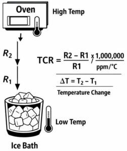
The basic procedure is to first measure the resistor at a reference temperature, usually 25°C. Then increase the temperature to a higher point, such as 85°C, allow the resistor to stabilize, and measure the resistance again.
TCR can be calculated using the following formula:
TCR (ppm/°C) = [(R₂ − R₁) / R₁] × [1 / (T₂ − T₁)] × 10⁶
For example, suppose a 10 kΩ resistor measures 10,000 Ω at 25°C and 10,062 Ω at 85°C. In that case, the calculated TCR is about +103 ppm/°C, which is close to the expected range for a standard ±100 ppm/°C resistor.
If the measured TCR is much higher than expected, it may indicate problems such as thermal damage, mechanical stress, aging, or part quality issues. In some cases, the resistor may also show unstable or non-linear behavior across temperature, which suggests that the part is no longer performing normally.
Some resistors change value slightly when voltage is applied across them. This effect is called the voltage coefficient of resistance (VCR), and it is separate from temperature-related resistance change.
VCR is typically expressed in ppm/V. In general, thick film resistors tend to show a more noticeable voltage coefficient, while thin film, metal film, and wirewound resistors usually perform better in this area.
For example, suppose a 10 MΩ resistor has a VCR of -100 ppm/V and operates across 200 V. In that case, the resistance shift would be about -20,000 ppm, or -2%, relative to its low-voltage value. In a precision circuit, that level of change could be unacceptable.
To test VCR, the resistor is measured at a low voltage first, then measured again at higher applied voltages while monitoring both voltage and current accurately. The resistance at each step is calculated and compared. If the resistance changes systematically as voltage increases, the part has a measurable voltage coefficient that may affect circuit performance.
In precision applications, resistor noise can also be important. This is especially true in low-noise amplifiers, sensor front ends, instrumentation circuits, and other sensitive analog designs. In more general-purpose circuits, resistor noise is usually not a major concern.
One type of resistor noise is thermal noise, also called Johnson noise. It can be estimated with the following formula:
Vn = √(4kTRB)
Where:
- k is Boltzmann’s constant
- T is absolute temperature in Kelvin
- R is resistance in ohms
- B is bandwidth in hertz
At room temperature, a 10 kΩ resistor over a 10 kHz bandwidth produces about 1.3 µV RMS of thermal noise. Because this is a fundamental physical effect, it can only be reduced by lowering the resistance, temperature, or measurement bandwidth.
Another type is excess noise, often called current noise or 1/f noise. Unlike thermal noise, this depends strongly on resistor material and construction. Metal film and wirewound resistors usually have very low excess noise (usually below -30 dBs), while carbon composition and some thick film resistors tend to be noisier (usually -10 dBs or higher).
Testing for excess noise usually requires a low-noise amplifier, a spectrum analyzer or equivalent measurement system, and a stable DC bias current. The resistor is biased at a fixed current, and the noise is observed over a defined frequency range, such as 10 Hz to 10 kHz.
This type of testing is mainly used in precision, aerospace, and low-noise analog applications. For standard incoming resistor inspection, it is usually unnecessary.
Checking a single parameter is not always enough, especially when resistors are being evaluated in bulk for production use. A broader screening process helps identify parts that appear acceptable under normal conditions but may become unstable under thermal or environmental stress.
A typical screening process begins with a resistance measurement at room temperature. For low-value resistors, a four-wire method is recommended to improve accuracy. The measured value should be compared with the nominal resistance and recorded for reference.
The parts can then be exposed to an elevated temperature, such as 125°C, for a short period, for example 30 minutes. During or after the exposure, the resistance is measured again and compared with the original value. Any significant drift may indicate that the part is not suitable for reliable service.
Moisture sensitivity can also be evaluated. One common method is to expose the resistor to 85°C and 85% relative humidity for 48 to 72 hours, followed by another resistance measurement. If the resistor absorbs moisture or its protective coating is weak, the resistance may shift beyond the expected range.
Screening methods like these are useful for identifying parts with hidden reliability problems before they are assembled into the final product.
Proper resistor testing is not just about confirming a number on a meter. It is about understanding how a resistor behaves under real operating conditions, including temperature, humidity, voltage stress, and long-term use. A resistor that looks acceptable in a basic measurement may still create reliability problems in an actual product if those factors are ignored.
At PCBCool, quality control starts long before PCB assembly begins. As part of our manufacturing process, we carry out incoming material inspection to verify component quality before production. We also provide component sourcing services and can purchase parts according to customer-specified brands when required. Combined with our PCB manufacturing and PCB assembly services, this helps customers reduce supply risk, improve consistency, and build more reliable electronic products.