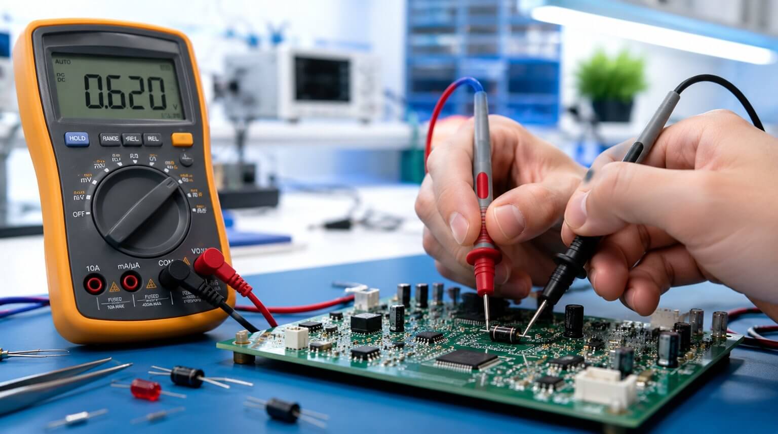
Diodes are fundamental components in almost every electronic device and are applied to produce different functions such as rectification, protection, radio frequency detection, clamping, voltage regulation, and so on. Properly testing diodes lets you quickly identify faults, avoid misdiagnosis and restore circuits reliably.
More often than not, diodes are usually the first components to get damaged in case of a fault in the circuit; thus, if you are able to identify this early enough, you can save time that could otherwise be wasted in troubleshooting.
This article gives you practical, step-by-step testing procedures covering common diode types, interpretation guidance, and safety tips you can apply when performing these tests.
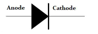
A diode, in simplest terms, is a two-lead semiconductor device that acts as a one-way gate for electric current. A typical p-n junction diode, such as a rectifier diode, is formed by joining n-type and p-type semiconductor materials together. This internal p-n junction allows current to flow more easily in one direction than the other, which is the basic principle behind diode testing.
When the diode’s anode lead is more positive in voltage than its cathode lead, we refer to this condition as forward biasing, i.e., current is allowed to flow through the device. However, if the polarities are reversed, i.e., the anode is made more negative in voltage than the cathode, a condition referred to as reverse biasing – the diode acts to block the current flow.
Some of the diode parameters include:
- Forward voltage (VF): this is the voltage drop when the diode is conducting, typically ≈0.6 – 0.8 V for diodes made of silicon; for Schottky diodes ≈0.15 – 0.5 V.
- Reverse leakage current (IR): this is the small reverse current when the diode is reverse-biased; it increases with temperature and damage to the diode.
- Zener breakdown voltage (VZ): this is the reverse voltage at which controlled conduction occurs.
- Junction capacitance (CJ): the typical amount of capacitance intrinsic to the junction, due to the depletion region acting as a dielectric separating the anode and cathode connections. This is usually a very small figure, measured in the range of picofarads (pF).
- Reverse recovery time (trr): this is the amount of time it takes for a diode to ‘turn OFF’ when the voltage across it alternates from forward-bias to reverse-bias polarity.
In diode testing, these parameters help explain why a diode may fail or produce abnormal readings. Typical diode failure modes include:
- Open: no conduction in either direction.
- Short: conducts in both ways.
- Leaky: characterized by excess reverse current.
- Shifted VF or VZ: signs of a degraded junction.
- Slower switching: increased TRR.
As part of safety precautions and preparation, consider doing the following:
- Always remove the power before probing.
- Discharge large capacitors; even small circuits can hold charge.
- When practical, test diodes out of circuit to avoid misleading parallel paths.
Ensure you have the necessary tools such as:
- Digital multimeter (DMM) with diode mode.
- Bench power supply with current limiting.
- Oscilloscope and function/pulse generator for dynamic and recovery tests.
- LCR meter for capacitance/varactor tests.
- Curve tracer or source-measure unit (SMU) for precision I-V characterization.
- Small-value resistors (1 kΩ – MΩ), breadboard or test jig.
- Soldering iron and de-soldering tools for removing SMDs.
- Relevant datasheets for the specific diodes.
When comparing your test results with the datasheet, remember that diode readings can change with temperature, applied bias, test current, and instrument resolution.
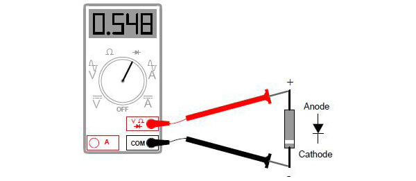
Diode test mode is usually the best approach to test your diode as it relies on the characteristics of the diode. During the test, the diode is put in forward bias and the voltage that is dropped across the diode is measured, using the digital multimeter. When a diode is in good condition, it will allow the current to flow in forward bias, and voltage drop will be produced.
To conduct a diode mode test, follow the procedure below:
- Ensure the power to the circuit is switched off before removing or testing the diode.
- You may remove the diode or lift one lead if in-circuit or if parallel paths exist.
- Set the multimeter to the diode test mode by turning the knob (diode mode is usually designated by a diode symbol on the multimeter).
- Connect the multimeter red lead to the diode anode and the black lead to the cathode.
- Read the forward voltage on the multimeter display. You should expect ≈0.6 – 0.8 V for the diodes made of silicon.
- Reverse the leads, record the measurement. The multimeter should show OL (open) or very high resistance. Some multimeters will display 1 to indicate an open circuit.
Resistance test mode can be used if the multimeter is not equipped with a Diode test mode or for additional checks after performing the diode test.
But, there are some caveats to take into consideration when using this method:
This method does not always show whether a diode is good or bad (if possible should be used to verify a diode status after a diode test shows a bad outcome); it should not be performed when a diode is connected in a circuit because it will produce a false reading.
To perform a diode test in resistance mode, follow the procedure below:
- Ensure the power supply to the circuit is switched off.
- Remove the diode from the circuit.
- Turn the knob on the multimeter to resistance mode.
- Connect the red probe to the anode and the black probe to the cathode (forward-bias state), then record the resistance reading.
- Reverse the probes (reverse-bias state), test again, and record the second reading.
When interpreting the readings, use the following guidance:
- If the multimeter displays a few hundred to a few kilohms in the forward-bias state, then the diode is functioning well; otherwise, very low resistance readings in tens of ohms indicate a bad diode.
- If there is low resistance in both directions, that is, in forward bias and reverse bias, it indicates a shorted diode.
- If there is very high or infinite resistance in both directions, it indicates an open diode.
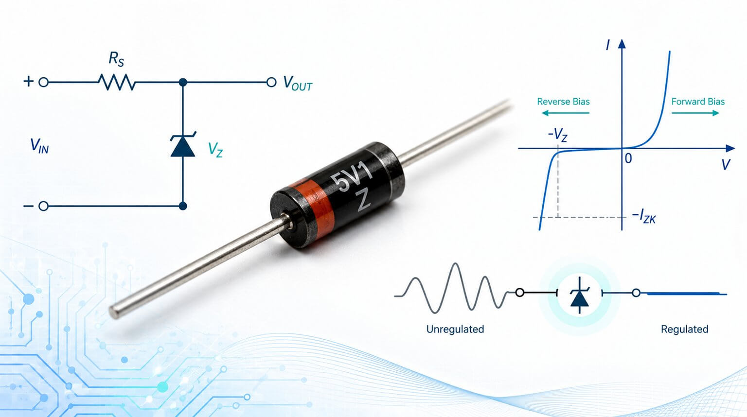
Before looking at the testing procedure, it is useful to understand how a Zener diode behaves, because its key function is different from that of a standard rectifying diode.
When forward-biased, Zener diodes behave in a similar manner as standard rectifying diodes, i.e., they have a forward voltage drop which follows the diode equation and is about 0.7 volts.
In reverse-bias condition, they do not conduct until the applied voltage reaches or exceeds the Zener voltage. At this point, the diode is able to conduct substantial current, and in doing so, it will try to limit the voltage dropped across it to that Zener voltage point. So long as the power dissipated by the reverse current does not exceed the diode’s thermal limits, the Zener diode will not be damaged.
Because a Zener diode conducts in reverse bias only when the applied voltage is higher than the Zener breakdown voltage, also referred to as the Zener voltage, an extra test circuit is needed.
The procedure for performing a test on a Zener diode is as follows:
- Identify the terminals of a Zener diode (anode and cathode).
- Connect an adjustable supply (bench supply recommended) through a series resistor sized to limit current: R = (Vsupply – expected Vz)/Iz_test.
- Put the multimeter dial in voltage mode.
- Apply reverse bias and measure the voltage across the Zener diode.
- Gradually increase the input supply voltage to the diode and observe the voltage readings on the multimeter display.
- The multimeter voltage reading should increase as the variable supply voltage is increased until the breakdown voltage of the diode.
- Beyond this point, the multimeter should display a constant value of voltage regardless of the input variable supply.
- If this happens, then the Zener diode is in good working condition; otherwise, it may be defective.
- Alternatively, compare the measured Vz at the test current to the datasheet Vz.
- Zener diodes are often paralleled by resistors or networked; if that is the case, remove the Zener diode under test for accurate Vz measurement.
If the voltage Vz across the Zener diode is significantly off from what is specified in the datasheet or if Vz is unstable with a small current change (i.e., high dynamic resistance), it indicates a defective Zener diode.
- Use an in-circuit digital multimeter for quick inspection of diodes. But consider removing the diode under test from the circuit if the results are ambiguous due to parallel paths or when precise characterization is required.
- Record the test current, temperature, instrument used, and the measured Vf/Vz and leakage current Ir for traceability.
- Use substitution testing – if you are unsure of the results, replace the suspect diode with a known good component (same or equivalent specifications) to confirm the fault quickly.
- When handling SMD diodes, use hot air or micro-soldering; minimize the heating time to avoid thermal damage. Consider room-temperature extraction tools or lift one leg for in-circuit tests.
- Avoid common mistakes such as applying power without series resistance to Zener diodes, trusting a digital multimeter in diode mode for varactors, TVS or photodiodes (use the appropriate instruments).
The decision flow should mirror the following:
- Basic flow/fail with a digital multimeter: If the diode is clearly shorted or open, replace it.
- Marginal readings (higher Vf, or elevated leakage): Perform controlled bench tests to quantify the deviation from the datasheet.
- If the results are out of specifications, replace and confirm the circuit functionality; if within specifications, investigate the surrounding components such as the resistors, transistors, capacitors, etc., that affect the diode operating point.
When to replace vs. further inspection:
- Replace immediately if the diode is shorted or open.
- If the diode tests are good but the circuit still misbehaves, look upstream or downstream components or intermittent/thermal faults.
- If uncertain but critical such as a Zener diode used for reference, replace and retest.
Diode testing is a small but important step in understanding whether a circuit is working as intended. A simple diode fault can affect power flow, signal behavior, or circuit protection, so accurate testing helps engineers identify problems earlier and avoid unnecessary component replacement.
In PCB and PCBA production, this same idea applies at a larger scale: testing should be part of the manufacturing process, not an afterthought. At PCBCool, our PCB assembly services include 100% AOI inspection and electrical testing to help ensure that assembled boards meet the expected quality requirements before delivery.