Traffic lights are something we see every day on the roads. They control the flow of vehicles and keep traffic moving in an organized way without accidents. Most people never think about how these lights actually work, but the idea behind them is quite simple once you break it down.
In this article, we will build a small model of a traffic light system using an Arduino Uno, a few LEDs, and a breadboard. This is one of the most common beginner projects in electronics and embedded systems because it teaches the basics of digital output control, timing, and circuit building, all in one simple project.
By the end of this article, you will understand how a real traffic signal works, how to wire the components together, how to write the code for it, and how to test it on your own Arduino board.
Anyone who is new to Arduino or electronics often struggles to find a project that is simple enough to understand but still teaches something useful. The traffic light project is perfect for this because it only needs a handful of parts, the wiring is not complicated, and the code is short and easy to follow. At the same time, it introduces some very important concepts such as:
- How to connect LEDs safely using resistors
- How digital pins on a microcontroller work
- How to control timing using delays
- How to structure a program using loops
These are the same building blocks used in much more advanced projects, so learning them here gives a strong foundation for anything else you might build later.
To build this project, you do not need many parts. Here is the full list:
- Arduino Uno board
- USB cable to connect the Arduino to a computer
- Breadboard
- Red LED
- Yellow LED
- Green LED
- Three resistors (220 ohms is a good value for LEDs)
- Jumper wires (male to male)
All of these parts are cheap and easily available from any electronics shop or online store. If you are a student or a hobbyist, you may already have most of these lying around from other small projects. For future business projects, PCBCool can also support component sourcing, helping customers manage BOM availability and procurement together with PCB assembly.
Before jumping into the wiring, it helps to understand the actual pattern that traffic lights follow in real life. A standard traffic signal has three colors, and each one has a meaning:
- Red means stop. Vehicles must not move.
- Yellow means get ready. The light is about to change, so drivers should slow down.
- Green means go. Vehicles are allowed to move.
The normal cycle in most countries goes like this: the light stays red for some time, then it turns green, then, before turning back to red, it briefly shows yellow as a warning. This cycle keeps repeating over and over again. Our Arduino project is going to copy this same pattern using LEDs instead of large traffic bulbs.
The wiring for this project is very simple because we are only working with three LEDs. Each LED needs to be connected to a digital pin on the Arduino through a resistor, and the other leg of each LED needs to be connected to the ground pin.
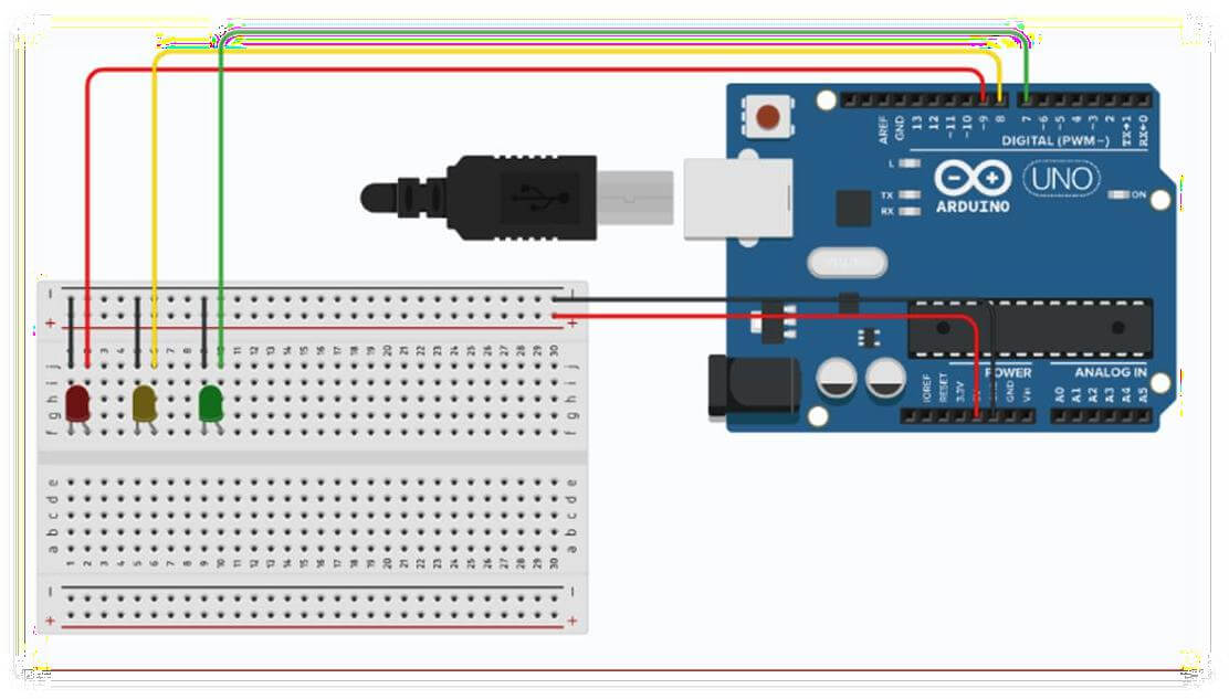
Below is the circuit diagram showing how everything should be connected. The red LED, yellow LED, and green LED are placed on the breadboard, and each one is wired back to the Arduino using colored jumper wires. Notice how the black wire runs along the bottom rail of the breadboard to provide a common ground connection for all three LEDs.
As shown in the diagram, the connections are:
- Red LED connected to digital pin 9
- Yellow LED connected to digital pin 8
- Green LED connected to digital pin 7
- All LED ground legs are connected to the Arduino GND pin through the breadboard’s ground rail
You can use different PINs if you prefer, just make sure the PINs in your code match the pins you actually wire up.
Here is a step-by-step way to build the circuit:
- Place the Arduino next to the breadboard so the wires can comfortably reach across.
- Insert the red, yellow, and green LEDs into the breadboard, keeping some space between them. Each LED has two legs, a longer one (positive) and a shorter one (negative).
- Connect a 220 ohm resistor to the longer leg (positive) of each LED. The resistor protects the LED from too much current, which could burn it out.
- Run a jumper wire from the other end of each resistor to the Arduino digital pins (9, 8, and 7 in our example).
- Connect the shorter leg (negative) of each LED to the ground rail on the breadboard.
- Finally, connect the ground rail on the breadboard to the GND pin on the Arduino using a single jumper wire.
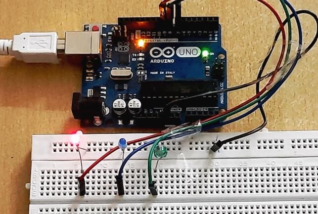
Once this wiring is complete, your breadboard and Arduino should look something like the picture below, showing the finished physical setup with all three LEDs connected and wired to the board.
In this picture, you can see the Arduino Uno powered through a USB cable, with jumper wires running down to the breadboard where the three LEDs are placed in a row. This matches exactly what we described in the circuit diagram, just in real physical form instead of a drawing.
Now that the hardware is ready, we need to write the program that will control the LEDs. The Arduino programming language is based on C and C++, but for a project like this, you only need to know a few basic commands.
Here is the complete code for the traffic light project:
Let us break down what each part of this code is doing:
- At the top, we declare three variables (redLED, yellowLED, greenLED) and assign them the pin numbers we used in our wiring. This makes the code easier to read and change later, since we do not have to remember PIN numbers throughout the program.
- The setup() function runs only once when the Arduino is powered on or reset. Inside it, we tell the Arduino that each of these three pins will be used as an OUTPUT, meaning the Arduino will send power out of these pins rather than reading power coming in.
- The loop() function runs over and over again, forever, as long as the Arduino has power. This is where the actual traffic light pattern happens.
- digitalWrite(redLED, HIGH) turns the red LED on by sending 5 volts to that pin. digitalWrite(redLED, LOW) turns it off by sending 0 volts.
- delay(5000) tells the Arduino to wait for 5000 milliseconds, which is 5 seconds, before moving to the next line of code. This is what creates the timing between each light.
Because the loop() function keeps repeating, the pattern of red, then green, then yellow, then back to red will continue endlessly, just like a real traffic signal.
You can change the delay values to make the lights stay on for shorter or longer periods, depending on how you want your model to behave.
Once you have written or copied the code into the Arduino IDE software on your computer, follow these steps to run it on your board:
- Connect the Arduino to your computer using the USB cable.
- Open the Arduino IDE and paste the code into a new sketch.
- Go to the Tools menu and select the correct board type, which should be Arduino Uno.
- Also, from the Tools menu, select the correct COM port that your Arduino is connected to.
- Click the upload button, which looks like an arrow pointing to the right.
- Wait for the IDE to show “Done uploading” at the bottom of the screen.
Once the upload is complete, your LEDs should immediately start following the traffic light pattern that we defined in the code.
After uploading the code, you should see the red LED light up first and stay on for 5 seconds. Then it will turn off and the green LED will turn on for another 5 seconds. After that, the green LED turns off and the yellow LED lights up for 2 seconds, warning that the cycle is about to restart. Then the entire pattern repeats itself from the beginning with the red light again.
If you test this setup in a darker room, the glow from the LEDs becomes much more visible and gives a nice effect similar to real traffic signal lights glowing at night. The picture below shows the LEDs glowing in a dim setting, which really highlights how the colors stand out once the surrounding light is reduced.
This kind of testing is also useful for confirming that your circuit is working correctly. If any of the LEDs do not light up, it usually means one of the following problems:
- The LED might be inserted backwards, since LEDs only work in one direction
- A wire might not be firmly connected to the breadboard or Arduino pin
- The resistor value might be too high, dimming the LED too much to notice
- The PIN in the code does not match the PIN used in the wiring. Going through this checklist usually solves most beginner wiring issues.
Once your basic traffic light is working, there are many ways you can expand this project to make it more advanced and realistic:
- Add a pedestrian crossing light using two more LEDs (red for stop, green for walk) that works opposite to the main traffic light.
- Add a push button so pedestrians can request the signal to change, just like real crossing buttons.
- Use an LCD screen to display a countdown timer showing how many seconds are left before the light changes.
- Control multiple traffic lights at an intersection, where one road has to be red while the other is green, and they switch together in sync.
- Add a buzzer that sounds during the yellow light phase as an extra warning signal.
These upgrades are not too difficult once you understand the basic version, and they are a great way to keep learning new Arduino skills, such as reading button inputs, using additional libraries, and managing multiple components working together at the same time.
The Arduino Uno-based traffic light project is one of the best ways for beginners to get comfortable with electronics and programming at the same time. It uses simple, affordable components, and the wiring is easy enough to complete in under thirty minutes. At the same time, the underlying concepts, such as digital output control and timing with delays, are used in countless other electronics projects, from home automation systems to robotics.