It is often assumed that once a customer has specified the connector models and fixed the mounting holes in an LED project, it leaves the PCB partner nothing to design. But is that really the case?
PCBCool recently received a request: design a control circuit that met the required functions while keeping the DC terminals, switch, board outline, and screw-hole layout completely unchanged, and then turn that design into a working PCBA prototype.
This case challenges that common assumption. In fact, the tighter the external constraints, the more engineering experience is often required for the internal circuit design and PCB layout. Let us take a closer look at the project and how we approached it.
The customer is an Australian systems integrator that installs smart-home and building-automation systems. For one of its projects, it needed a custom linear LED light engine built around an existing mechanical design.
The project began with a controlled drawing—Part 51526, “80173 LED Board, PCBA,” REV 1.0—and a short specification that established several fixed requirements. The DC input connectors were specified by exact part number: WAGO 2060-451 with 998-404. The tactile switch was also predetermined: a right-angle, surface-mount C&K KT11B2SAM35LFG with a 10 mm actuator.
Four elements could not be changed:
- Connector type and location
- Switch location
- Board outline
- Screw-hole positions
Everything else—including the control circuit, LED count, component selection, and PCB layout—had to be developed around those fixed points.
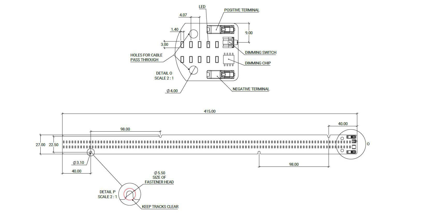
The main challenge was fitting all required electrical and control functions into a fixed mechanical envelope. The PCB is a 415 mm-long strip, only 27 mm wide, with an effective routing band of 22.5 mm. At one end, the board expands into a 40 mm circular control head that had to accommodate the positive and negative terminals, the switch, and the control components. Applicable general mechanical tolerances followed ISO 2768-1 class m.
The functional scope also expanded during development. What began as a single-switch dimming concept evolved into a two-channel white-and-amber system with independent control and state memory. These additional functions had to be integrated without changing the approved board outline or any of the fixed component positions.
PCBCool treated the customer’s fixed interfaces as design anchors rather than obstacles. The approach was straightforward: lock the mechanical requirements first, then develop the control circuit and PCB layout around them.
The core deliverable was a dual-channel control system with separate white and amber outputs. Each channel could be switched on independently, while holding the corresponding control dimmed that channel linearly. Running both channels together produced a warmer blended light, and the board retained its previous state after power cycling.
At the functional level, the architecture remained direct: a 12 VDC input feeds a two-channel switching and dimming stage, which then drives the white and amber LED strings independently. The specific dimming method and control components are protected by NDA and are therefore not disclosed in this case study.
With an effective routing width of only 22.5 mm, current-path planning was a functional requirement rather than a cosmetic consideration. The 40 mm circular control head had to accommodate both WAGO terminals, the tactile switch, and the control components while still preserving sufficient copper for the LED channels.
Each Ø3.10 mm mounting hole required a Ø5.50 mm fastener-head keep-out area, together with a separate keep-tracks-clear zone. These exclusions were incorporated into the layout from the beginning rather than corrected after routing. Cable pass-through holes were also positioned to allow field wiring to exit cleanly.
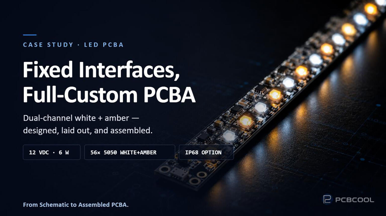
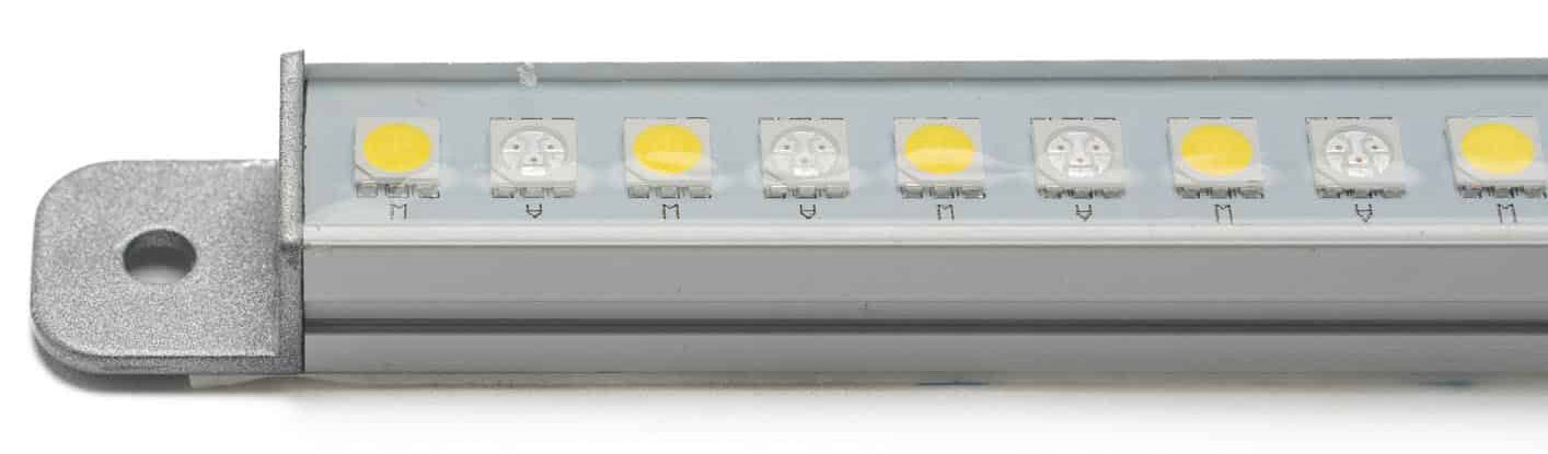
The board carries 56 5050 LEDs arranged in alternating 5000 K white and amber positions. Interleaving the two channels along the full length of the board creates a more uniform color blend and avoids visible sections of separate white and amber light.
The WAGO SMD terminals, right-angle C&K switch, control components, and all 56 LEDs were designed for SMT placement and reflow soldering within one consistent assembly process. Keeping circuit design, PCB layout, fabrication, and assembly within one coordinated workflow also allowed DFM feedback to be incorporated directly into each revision rather than passed between separate design and assembly suppliers.
Beyond the PCBA itself, PCBCool can also complete the finished linear light engine. The board is designed to fit inside a 535 × 16 × 13 mm silver, powder-coated extruded-aluminum housing with cast-aluminum mounting tabs and an IP68 sealing structure.
This box-build option allows the customer to source the PCBA and finished lighting unit through one coordinated supplier instead of qualifying a separate vendor for final mechanical assembly.
The final drawing set and assembled board provide the clearest evidence of the design work. The completed PCBA operates at a measured 12 VDC, 0.5 A, and 6 W. The key parameters that defined the layout are summarized below:
| Parameter | Value |
|---|
| Board envelope | 415 mm × 27 mm, with a 22.5 mm effective routing band |
| Control head | Ø40 mm, accommodating the terminals, switch, and control components |
| Mounting | Ø3.10 mm holes, Ø5.50 mm fastener-head keep-outs, and keep-tracks-clear zones |
| Emitters | 56 × 5050 LEDs, with interleaved 5000 K white and amber channels |
| Electrical | 12 VDC / 0.5 A / 6 W |
| Control | Two-channel white and amber control, linear dimming, and state memory |
| Fixed components | WAGO 2060-451 / 998-404; C&K KT11B2SAM35LFG |
The design passed review after three iterations. Rather than restarting from the beginning, each revision brought the mechanical constraints, electrical requirements, and user-control functions into closer alignment. The third revision was approved by the customer.
Reliability was addressed throughout the PCBA process rather than left to final inspection. Each assembled board underwent 100% functional testing, covering power-on performance, the white channel, the amber channel, combined operation, switch response, linear dimming, and memory recall.
Photometric verification included correlated color temperature, luminous flux, color rendering, color difference, and beam uniformity. Chromaticity and color-temperature results were evaluated against ANSI/NEMA C78.377, while the remaining optical parameters were checked against the project-specific criteria agreed with the customer. When finished-unit assembly was included, each luminaire also underwent an IP68 water-ingress test before shipment. Detailed test thresholds remain protected under NDA.
The checks were performed in sequence: electrical function first, followed by optical performance and, where applicable, ingress protection. This approach allowed defects to be identified at the earliest practical stage, before the PCBA was sealed inside the housing, where removal and replacement would be more difficult and costly.
Following three rounds of design refinement, the customer approved the final revision and placed an order for 20 prototypes with a 14-working-day lead time.
The client’s Managing Director commented:
Your team is always quick to respond, and the engineering is very professional. I feel like if there was ever any issue, it would get resolved quickly.
Across more than 5,200 completed projects, PCBCool has supported a wide range of LED applications, including linear lighting, LED control boards, aluminum PCBs, and complete LED PCBA assemblies. If you are developing a custom LED product or need support with circuit design, PCBCool’s LED project solutions can provide a reliable path from concept to production.