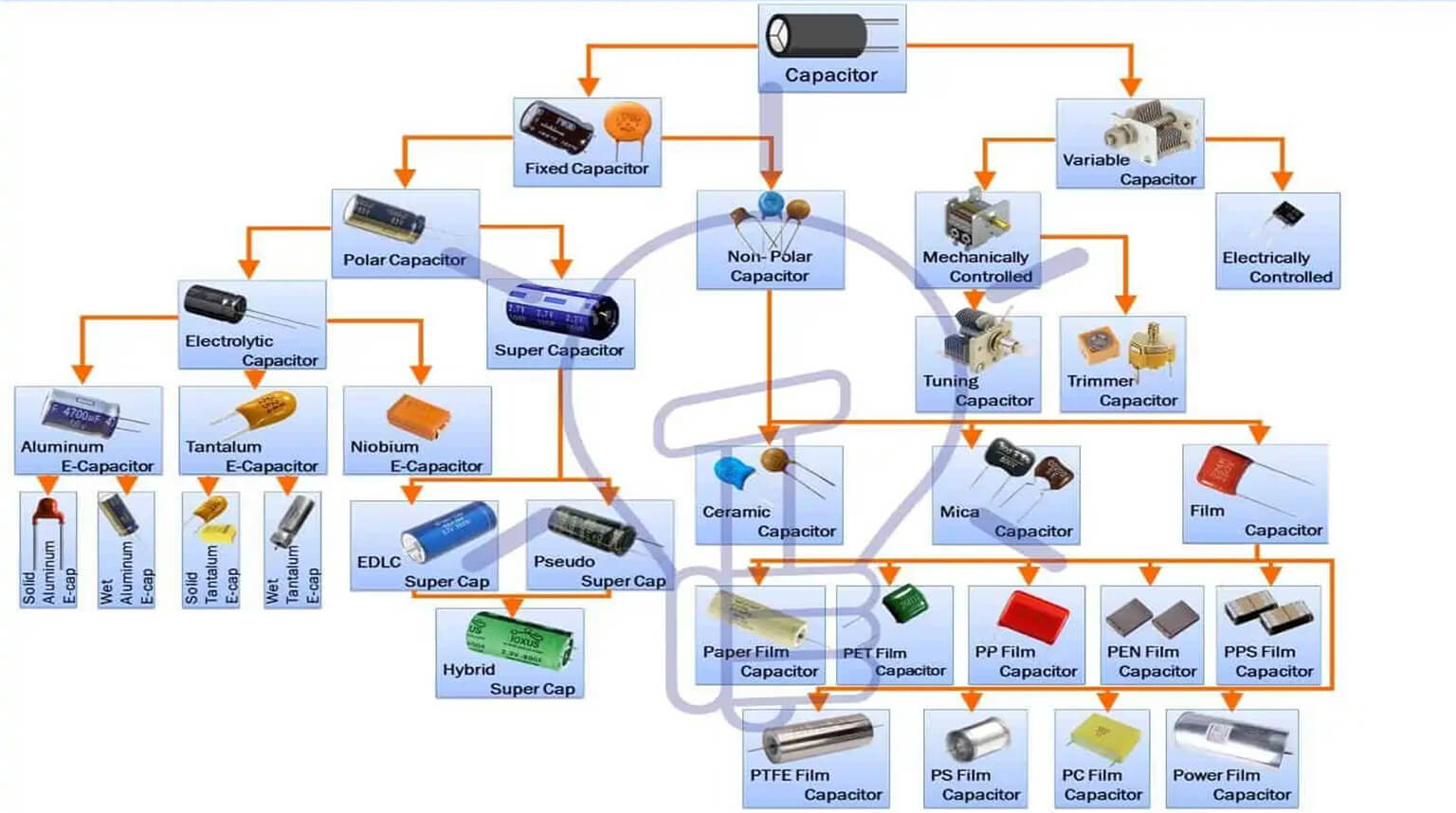
Capacitors are used to store electric charge in the form of an electric field. They can retain dangerous voltages even after power is removed.
If touched, a charged capacitor can deliver a sudden, potentially harmful pulse of current, causing electric shock, burns, or equipment damage. Large or high-voltage capacitors can also arc, explode, or reignite circuits.
Understanding how to safely discharge a capacitor is essential for maintaining electrical safety, preventing electrical shocks, and protecting components or circuits from damage.
In this article, we look at the fundamental concepts of charging and discharging capacitors, key safety precautions, step-by-step capacitor discharging methods, and proper handling and disposal after discharge.
A capacitor is made up of two conductors separated by an insulator, usually referred to as the dielectric, which stores electric charge. When the capacitor is connected to a battery or a DC voltage source, current will flow and the charge on the capacitor will increase until the voltage across the capacitor, determined by the relationship C = Q/V, is enough to stop current from flowing in the circuit.
When a capacitor is connected to a DC voltage source, as described above, it will charge up almost instantaneously. In the same way, a charged capacitor that is shorted with a wire will discharge almost instantaneously. But with some resistance added, the rate of charge or discharge follows an exponential pattern.
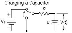
When charging a capacitor through a resistor, the voltage across the capacitor with respect to time is given as:
V(t) = Vs(1 – e^(-t/RC)) Charging RC
Where:
- V(t) is the capacitor voltage in volts at time t.
- Vs is the source voltage.
- t is the time in seconds after the source voltage is applied.
- e = 2.718, the base of natural logarithms.
- R is the circuit resistance in ohms.
- C is the capacitance in farads.
The number e, also known as Euler’s number or the base of natural logarithms, appears in any equation in which the rate of increase or decrease of a quantity depends linearly on the amount of the quantity. In this case, the rate at which the capacitor charges depends on the current, which decreases as the charge, and hence the voltage, on the capacitor increases.
Theoretically, the charging process never really finishes, but eventually the charging current drops to a negligible value. In other words, it takes an infinite amount of time for the current to actually decrease to zero or for the capacitor to become fully charged. This is a property of exponential functions. The exponential behavior is characterized by the time constant τ.
The time constant has units of seconds. The larger the product RC, the longer it will take the capacitor to charge to any fraction of its maximum value.
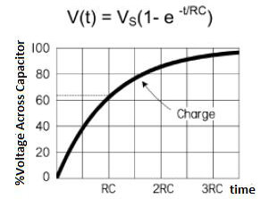
A convention used every so often is to let t = RC, which makes V(t) = 0.632 Vs. The RC term is called the time constant of the circuit and is the time in seconds needed to charge the capacitor to 63.2% of the supply voltage. The lowercase tau (τ) is usually used to represent RC: τ = RC.
After two time constants (t = 2RC = 2τ), the capacitor charges another 63.2% of the difference between the capacitor voltage at one time constant and the supply voltage, for a total change of 86.5%. After three time constants, the capacitor reaches 95% of the supply voltage, and so forth, as demonstrated in the graph in Figure 2 below. After five time constants, a capacitor is considered fully charged, having reached 97.24% of the source voltage.
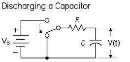
If we change the switch position as shown in Figure 3 below, the current will flow through the resistor, discharging the capacitor.
For a discharging capacitor, the following equation is used:
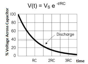
V(t) = Vs e^(-t/RC) Discharging RC
The above expression is basically the inverse of the previous expression for a charging capacitor. After one time constant, the capacitor voltage will have dropped by 63.2% from the supply voltage, so it will have reached 37.8% of the supply voltage. After five time constants, the capacitor is considered fully discharged; it will have dropped 99.4%, or down to 0.76% of the supply voltage.
You need to identify the capacitor and its basic features before discharging it.
You can perform the following tasks:
- Read the markings for voltage and capacitance. If the markings are unclear, look up the device schematic or service manual.
- Note the polarity for electrolytic capacitors, including the positive and negative terminals.
- Determine if the capacitor is connected to components that can recharge it, such as power supplies, switching regulators, or other parts of the circuit.
Most capacitors feature two terminals, which are essential for connecting to the circuit. Some capacitors have three terminals, such as dual run capacitors, which allow connections to both the compressor and fan in HVAC systems.
For two-terminal capacitors, the positive terminal may be identified by markings such as a plus (+) sign or by the length of the leads. Often, the longer leg is positive and the shorter leg is negative.
Three-terminal capacitors are typically marked as “C” for common, “H” or “HERM” for the hermetic compressor, and “F” or “FAN” for the fan.
To perform the task of discharging a capacitor effectively, ensure you have the following items:
- Multimeter with insulated probes.
- Insulated discharge resistor(s) and clips, or a commercial discharge tool.
- Insulated pliers and insulated gloves rated for the expected voltage.
- Safety glasses.
- ESR meter, optional for capacitor health checks.
Before working on or handling anything, always ensure that the power to the system the capacitor is part of is completely switched off.
As part of your preparation for the process, and to maintain your safety and that of the equipment, do the following:
- Switch off and unplug the device. Remove the batteries and isolate the power sources.
- Wear PPE, including insulated gloves rated for the expected voltage and safety goggles for high-energy cases.
- Work on an insulating surface and keep tools insulated.
- Use the one-hand rule around high voltages, keeping the other hand away from the circuit.
- Use a properly rated multimeter and test leads.
- If you are uncertain about handling very high voltages, get professional help.
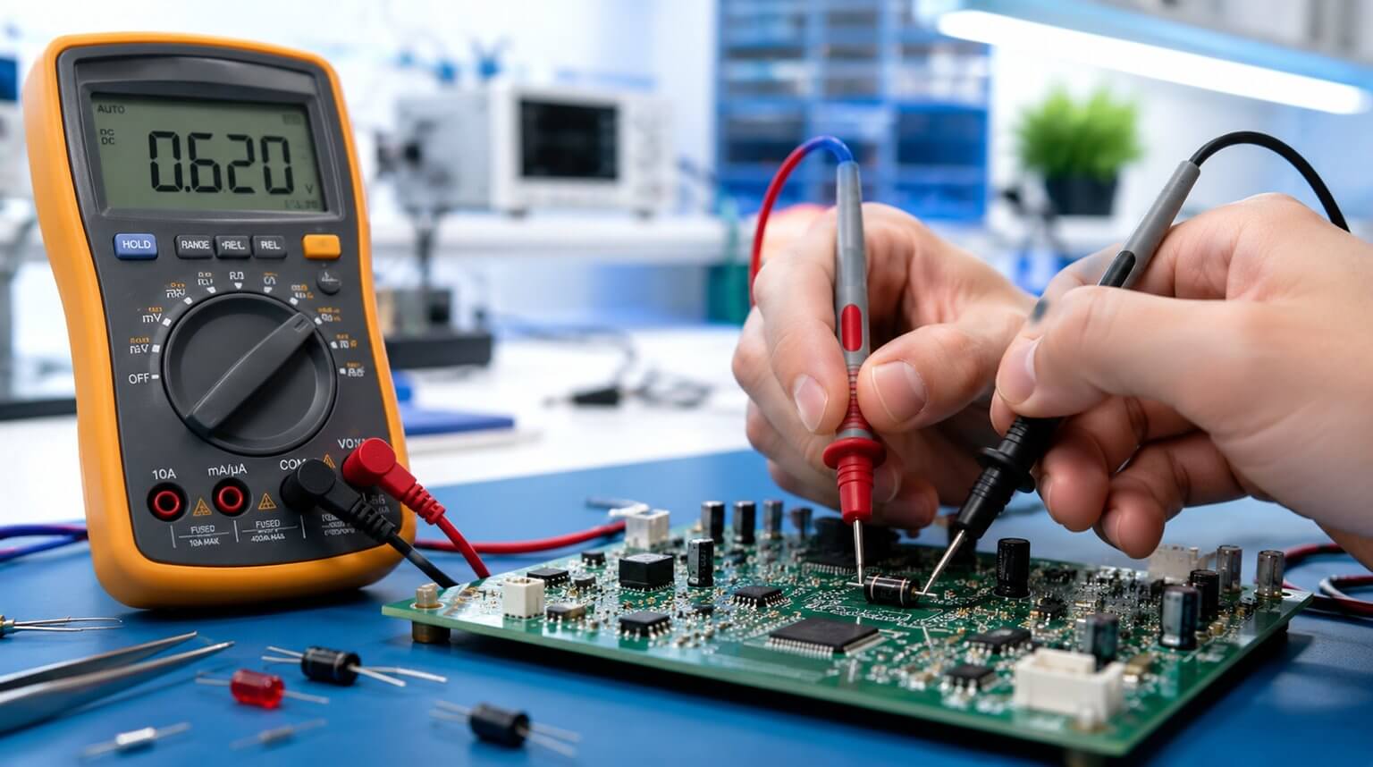
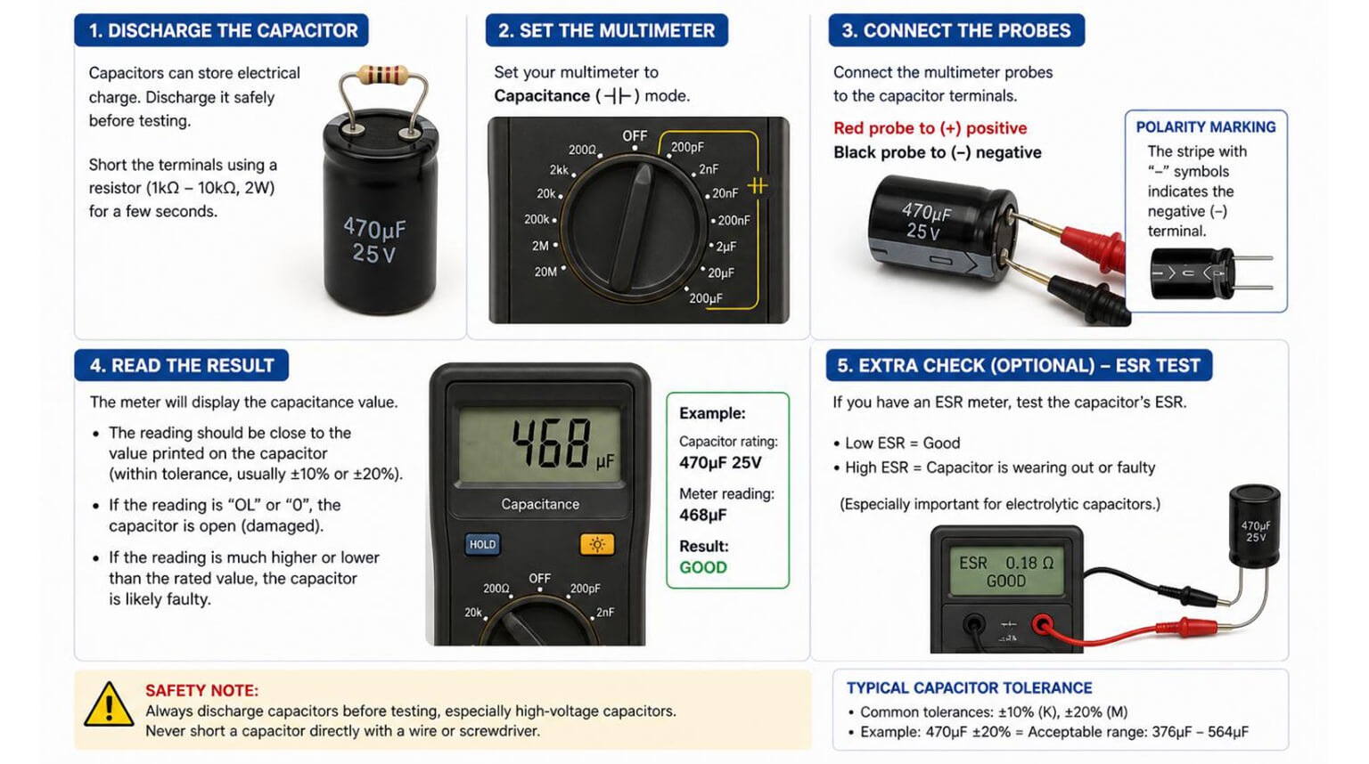
With the power source removed or switched off and the device isolated, measure the capacitor’s voltage using a multimeter on an appropriate DC range.
Use the one-hand rule for higher voltages and insulated probes.
Even if your meter reads 0 V, proceed cautiously. Circuits can sometimes re-energize capacitors.
This technique is controlled and safe for energy dissipation.
First and foremost, choose a resistor value. A typical range is 1 kΩ – 100 kΩ, depending on voltage, capacitance, and the desired discharge time.
Choose the power rating by calculating the worst-case initial power:
P = V² / R
Then choose a resistor, or a series/parallel resistor chain, with adequate wattage.
For example, for a 400 V, 100 µF capacitor, a 10 kΩ, 5 W resistor gives an initial current of 40 mA and a discharge time constant of:
τ = RC = 10 kΩ × 100 µF = 1 s
This means approximately 5τ, or 5 seconds, to reach about 1%.
Follow these steps:
- Attach insulated leads or crocodile clips to the resistor.
- Securely connect the resistor across the terminals. Hold it with insulated pliers if necessary.
- Monitor the voltage with a multimeter until it reads near 0 V.
- Leave the resistor connected briefly after reaching 0 V to catch any rebound.
After the resistor discharge and a meter reading of approximately 0 V, you may momentarily short the terminals with an insulated screwdriver to ensure zero voltage. For large capacitors, it is preferable to do this with a resistor in series.
For smaller capacitors under 50 V, you may ignore this step if you are confident with the result. Optionally, verify with a second meter reading.
You can use a well-insulated screwdriver to discharge a capacitor. Note that directly shorting large or high-voltage capacitors can produce dangerous sparks and cause damage.
Only use direct shorting for small capacitors, such as those under 50 V and with low capacitance, or after the resistor discharge method.
Follow these steps:
- Using the screwdriver, touch the metal shaft simultaneously to both capacitor terminals.
- Hold the screwdriver in place for a few seconds to allow the capacitor to discharge.
- Use a multimeter with a voltage setting to check whether the capacitor has discharged completely.
- Place the multimeter probes across the terminals of the capacitor and make sure the voltage is zero or very close to zero.
This is appropriate for applications such as routine HV work. Use a purpose-built discharge tool with an integrated resistor and insulated leads according to the manufacturer’s instructions.
Follow these steps:
- Switch off the power and isolate the device, such as by unplugging it, removing batteries, or disconnecting power sources.
- Verify that the tool’s ratings match or exceed the capacitor’s voltage and stored energy.
- Measure the capacitor voltage with a multimeter to confirm whether it is charged.
- Attach the tool’s insulated clips to the capacitor terminals. Put the positive clip to the positive terminal, and the negative clip to the negative terminal or chassis ground as appropriate. Ensure firm metal contact.
- Engage the tool according to its instructions. Many tools have a switch or press-to-discharge button that applies an internal resistor. Maintain a safe distance while it operates.
- Wait for the recommended dwell time after discharge, following the tool manual. Some tools indicate completion with a lamp or meter.
- Recheck the capacitor voltage with your multimeter across the terminals. If voltage remains, repeat the discharge procedure.
- Keep the tool connected for a short time after the meter reads approximately 0 V to catch rebound, and then remove the clips.
- If the capacitor is to remain out of service, tape or insulate the terminals, or leave a bleed resistor connected.
Some designs include bleed resistors that discharge capacitors after power removal.
Verify this by measuring the voltage over the expected time. Do not presume a bleed resistor is present or sufficient without confirmation.
Follow appropriate safety precautions when using a multimeter to verify a capacitor.
- Ensure that the power is switched off and the device is unplugged before working on anything.
- Set your multimeter to the appropriate voltage range.
- Place the multimeter probes across the terminals of the capacitor.
- Confirm that the voltage is zero or very close to zero.
- If voltage remains, discharge the capacitor using a properly rated resistor or discharge tool, then measure again.
You can get rid of any residual charge by using an insulated grounding wire, when appropriate.
Follow these guidelines when disposing of or handling capacitors after discharging them:
- If the capacitor is damaged or leaking, follow local regulations for electronic waste and hazardous materials.
- For safe storage, keep discharged capacitors shorted, or tape the terminals and label them.
- When reusing a capacitor, verify its capacitance, ESR, and leakage with the appropriate test equipment.
Discharging a capacitor safely is not just about removing stored energy. It is about doing it in a controlled, predictable, and verifiable way. Whether you use a discharge resistor, a dedicated discharge tool, or an approved service procedure, the key is to avoid uncontrolled short circuits and always confirm the remaining voltage before handling the circuit.
For engineers, technicians, and manufacturers, capacitor safety also begins before the device is powered on. Choosing the right capacitor type, voltage rating, tolerance, ESR, and supplier source can reduce failure risks and improve long-term circuit reliability.
At PCBCool, we support PCB assembly projects with component sourcing services based on customer-approved brands, specified part numbers, and qualified cooperative suppliers. This helps ensure that capacitors and other electronic components used in production meet the required electrical performance, reliability, and project specifications.