Athlete protection is no longer only about treatment after an injury. More sports teams now use continuous data analysis to understand physical condition, recovery status, and health risks before problems become serious.
A European sports performance startup came to PS Electronics with this idea in mind: a custom wearable wristband that could support continuous athlete monitoring in real training environments.
The concept was familiar, but the requirements were not. What looked like a simple no-display sports wristband quickly became a complex engineering project involving signal stability, waterproofing, skin-contact materials, and long-term wearing reliability.
So, how did PS Electronics handle it?
Commercially available wearables from established players track three to six biomarkers at ±10–20% accuracy. Professional fatigue modeling and injury-risk prediction for athletes require ±5% or better across concurrent parameters.
For this project, an off-the-shelf wearable was not enough. Their requirements included:
| Requirement Area | What the Customer Needed |
|---|
| Biomarker monitoring | Continuous measurement of HR, HRV, skin temperature, SpO2, blood pressure based on PPG and PTT, and GSR |
| Product form | No-display wristband form factor |
| Branding | OEM colors, logo, and interchangeable bands |
| Data transmission | Continuous BLE transmission to the club’s own backend infrastructure |
| Waterproofing | IP68 water immersion rating |
| Skin-contact safety | ISO 10993 skin-contact biocompatibility testing |
The engineering problem was not any single line on that list. It was how these requirements interacted inside one compact wristband.
- GSR acquires biopotential signals in the microvolt range at 0.5–50 Hz — a frontend that is acutely sensitive to ground noise from adjacent sensors and switching regulators sharing the same PCB plane.
- IP68 sealing requires hermetic bonding materials that must simultaneously pass ISO 10993-5 cytotoxicity screening; not all high-performance sealants qualify.
- The rigid-flex PCB must sustain more than 100,000 bend cycles at the wrist joint per IPC-6013E Class 3, while maintaining controlled-impedance traces for the BLE antenna.
In other words, this was not simply a sensor selection project. It was a system-level engineering problem.
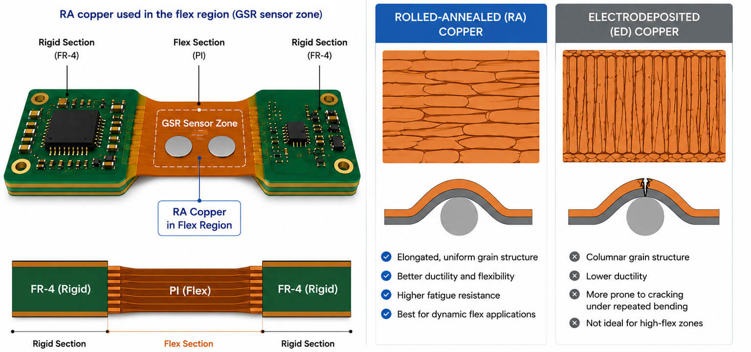
The PCB stack used a polyimide (PI) and FR-4 hybrid construction, qualified to IPC-6013E Class 3. The GSR sensor zone used a 4–6 layer structure with rolled-annealed (RA) copper foil through the flex region.
RA copper was selected because the wristband had to withstand repeated bending during daily use. At a 3T minimum bend radius, RA copper can support flex fatigue beyond 100,000 bend cycles, offering significantly better fatigue resistance than standard electro-deposited (ED) copper under the same bending conditions.
This is not an over-spec: IPC-6013E Class 3 requires demonstrated long-term flex reliability for dynamic bending applications, and wrist-worn devices qualify as dynamic by definition
GSR signal traces were routed within the flex zone, with no copper crossings at the bend centerline, following IPC-2223 design principles. A continuous ground plane copper pour was used to help shield the GSR analog domain from the switching power stage on adjacent rigid sections.
The rigid-flex architecture also eliminated the ZIF or FPC connector that would normally connect a separate flex cable to a rigid board. In a device designed for 100,000+ bend cycles and daily sweat exposure, that connector would become one of the highest-risk mechanical failure points.
Removing it was a reliability decision, not a cost decision.
GSR measurement applies a constant DC excitation below 0.5V across two Ag/AgCl dry electrodes on the inner wristband surface, then measures the resulting current to derive skin conductance.
The instrumentation amplifier was designed around the following targets:
| Parameter | Spec |
|---|
| Noise floor | <5 μVrms, 0.1–10 Hz |
| Input impedance | >1 GΩ |
| CMRR | >110 dB |
| ADC resolution | 24-bit sigma-delta |
| Bandpass | 1–40 Hz, active filter |
These specs are referenced against IEC 60601-2-47, which governs ambulatory electrocardiographic equipment and defines baseline performance floors for wrist-worn biopotential sensors.
Electrode material was also critical. Ag/AgCl maintains stable interfacial impedance in NaCl electrolyte environments, which is close to the condition created by sweat. Stainless steel or nickel electrodes can develop unstable polarization potentials under sustained perspiration contact, causing DC offset drift and corrupting the conductance baseline.
For a wristband worn continuously during training, measurement stability under sweat is not an edge case. It is part of the normal operating environment.
Ag/AgCl was therefore not a premium option. It was the practical baseline for stable GSR measurement.
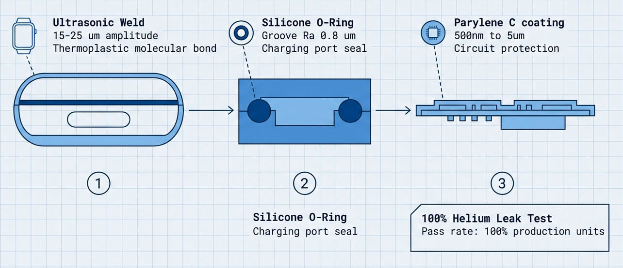
The main housing used ultrasonic welding at 15–25 μm amplitude to create a molecular bond between thermoplastic enclosure halves. This helped avoid adhesive or sealant compounds that could outgas or leach under body-temperature cycling — meets ISO 10993 biocompatibility standards.
For the charging interface, PS Electronics used a medical-grade silicone O-ring in a groove machined to Ra ≤ 0.8 μm. Critical circuit regions received Parylene C conformal coating at 500 nm to 5 μm as a secondary barrier against perspiration ingress through micro-pathways.
Two process controls govern waterproof assurance:
- IP68 test depth had to be defined in writing before tooling commitment. IEC 60529 specifies the IP test method, but IP68 depth and duration are product-specific.
- 100% helium mass spectrometry leak testing (He leak rate ≤ 1×10⁻⁸ Pa·m³/s) was used instead of relying only on end-of-line immersion sampling.
The wireless stage used BLE 5.0 LE 2M PHY with Data Length Extension enabled. This expanded the per-packet payload from the traditional 20 bytes to 244 bytes. ATT MTU was negotiated to ≥247 bytes.
At 100–400 ms connection intervals, practical throughput reached 500–800 Kbps.
This mattered because six-channel sensor data can quickly exceed the limits of older BLE 4.x packet structures. With a 20-byte payload, data must be split across multiple packets, increasing radio-on time, latency, and battery consumption.
LE 2M PHY with Data Length Extension solved the problem at the protocol level instead of relying on application-layer workarounds.
The BLE antenna was routed on the rigid PCB zone, away from the flex region and isolated from the analog frontend ground plane to reduce coupling risk.
| Parameter | Measured Value |
|---|
| Amplifier noise floor | <5 μVrms, 0.1–10 Hz |
| Input impedance | >1 GΩ |
| CMRR | >110 dB |
| ADC resolution | 24-bit sigma-delta |
| Signal bandpass | 1–40 Hz, active filter |
| Parameter | Result |
|---|
| Bend cycles completed | >100,000 |
| Minimum bend radius | 3T |
| Pass criterion | No fracture; ΔR <10% |
| Parameter | Specification |
|---|
| O-ring groove surface finish | Ra ≤ 0.8 μm |
| Ultrasonic weld amplitude | 20 μm |
| Helium mass spectrometry leak rate | ≤1×10⁻⁸ Pa·m³/s, 100% units |
| Parameter | Value |
|---|
| PHY | LE 2M |
| DLE payload | 244 bytes |
| ATT MTU | 247 bytes |
| Practical throughput | 500–800 Kbps at 200 ms interval |
For this type of wearable device, quality control could not be left until final inspection; rather, it must be rigorously controlled at every stage of the production process.
ISO 13485 governed the production quality management system from incoming materials to outgoing inspection.
All skin-contact materials, including silicone compounds, Ag/AgCl electrode stock, and Parylene C source material, required a certificate of conformance and safety data sheet traceable to the production lot.
This was not just paperwork. ISO 10993-related test results are tied to the tested material formulation and representative production lots. A production switch to a different silicone formulation, even from the same supplier, can invalidate previous test assumptions.
During production, PS Electronics applied process inspection and functional checks before final housing assembly.
Key controls included:
- AOI on every SMT process
- X-ray inspection for BGA and fine-pitch components
- 100% board-level verification of the GSR analog frontend before housing assembly
- Electrode contact impedance check at 1 kHz
- Instrumentation amplifier offset calibration
- ADC linearity check against a calibrated reference signal
Testing the GSR frontend before sealing was important. Once the product is welded, coated, and waterproofed, rework becomes difficult and costly.
Outgoing quality control focused on whether each unit could meet the customer’s functional and environmental requirements after assembly.
Key checks included:
- IP68 immersion at the customer-specified depth and duration, documented per unit
- 100% helium leak check before immersion
- BLE RF output power and receiver sensitivity measurement
- Functional aging for 4 hours at 40°C to simulate the thermal load of a training session
ISO 10993-5 cytotoxicity and ISO 10993-10 sensitization testing were handled through an accredited third-party laboratory using production-representative material lots, with traceability maintained through the quality documentation process.
During the project discussion, the client’s hardware lead stated:
“GSR would also be a great value to us.”
For PS Electronics, this was a meaningful confirmation. It showed that the customer valued the engineering input provided during the early review stage, not only the final manufacturing capability.
PCBCool is the digital marketing brand of PS Electronics, created to make our PCB, PCBA, and electronics manufacturing services easier for global customers to access. Behind PCBCool is the same manufacturing system that supports 1-6-layer FPC, 1-40-layer rigid board, and certification system.
If you are working on a similar wearable, IoT sensor, or medical-adjacent electronics project, feel free to contact PCBCool to discuss your design, manufacturing route, and production requirements.