In 2024, I was called to troubleshoot a failed irrigation controller in Nakuru, a town in Kenya. The board had no schematic, no labels, and a charred 6-pin IC with only “K17” visible. The local technician had already replaced it with a “similar” part, and ended up frying the microcontroller.
This isn’t rare. Across East Africa, many field repairs involve unknown or misidentified components—not because engineers lack skill, but because modern SMD parts often omit full part numbers, use cryptic codes, or are outright counterfeits.
You can’t fix what you can’t identify or understand.
This guide delivers a systematic identification protocol—not just “resistor = stripes,” but how to decode:
- 3-letter SOT-23 codes with no datasheet
- Burnt components with zero markings
- Fake ICs with swapped logos
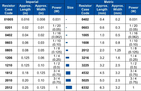
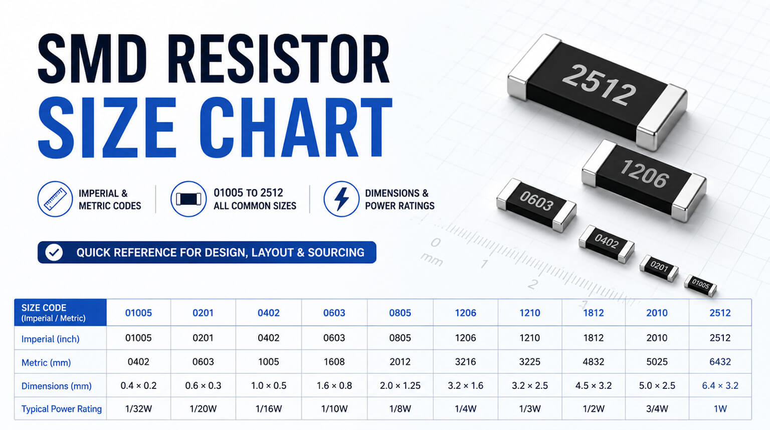
- Unmarked passives in 0201 packages
No guesswork. Just forensic techniques that work in dusty workshops, humid labs, and under deadline pressure.
Never start with a multimeter—start with context:
- Package Type → Narrows the possibilities to roughly 10–50 functions
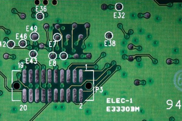
- Position on Board → Reveals likely role (e.g., near USB = ESD protection)
- Markings → Even partial codes can often be matched
- Circuit Topology → Adjacent components hint at function
- Failure Symptoms → Shorted? Open? Thermal damage?
Real Win:
A “mystery” 5-pin chip near a 24 V rail was identified as a current sense amplifier (TI INA180), not a voltage regulator, because it sat between a shunt resistor and an ADC.
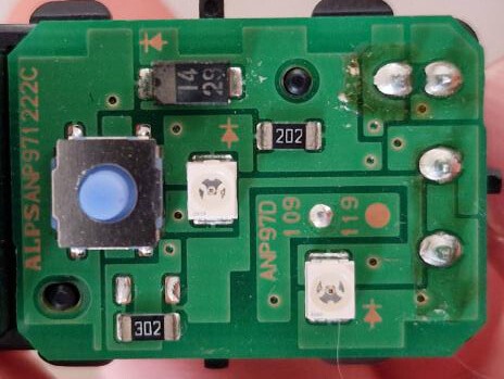
- 3-Digit Code: First two = value, third = multiplier (e.g., 103 = 10 × 10³ = 10 kΩ)
- 4-Digit Code (1% tolerance): 4701 = 470 × 10¹ = 4.7 kΩ
- “R” for Decimal: R47 = 0.47 Ω, 4R7 = 4.7 Ω
Caution:
Burnt resistors change value. Always de-solder one leg before measuring.
95% of ceramic capacitors have no markings. Identification relies on:
- Package Size: 0402 ≈ 0.01–1 µF; 1206 ≈ 1–100 µF
- Color: Brown ≈ X7R; Gray ≈ C0G/NP0 (typical, not absolute)
- Location:
- Near IC VCC → decoupling (0.1 µF typical)
- In power path → bulk (10–100 µF)
Pro Tip:
Use an LCR meter at operating frequency—capacitance can drop under high bias.
- Marking: Cathode band + code (e.g., M7 = 1N4007, BZ = BZV55-C3V3)
- SOD-323/SOD-523: Often just a color dot or letter
- TVS/ESD Diodes: CM12, SRV05—look for symmetrical placement on data lines
Failure Signs:
Shorted diode = low Ω in both directions; Open = infinite Ω
This is where engineers often get stuck. A 3-pin SOT-23 marked 1A could be:
- BC847 (NPN)
- PMBT3904 (NPN)
- DMG2307 (P-channel MOSFET)
Resolution Protocol:
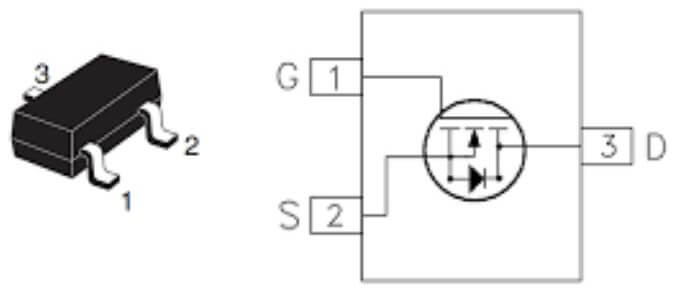
- Check Pinout:
- B-C-E = bipolar
- G-D-S = MOSFET
- Measure In-Circuit:
- Bipolar: ~0.6 V B-E drop
- MOSFET: Diode drop D-S, G = open
- Use SMD Codebook:
- Cross-reference with SMD Code Finder (offline database)
Critical:
Many MOSFETs use manufacturer-specific codes—for example, K17 corresponds to AO3401A from Alpha & Omega.
- Full Part Number: Best case (e.g., LM358DR)
- Top-Mark Code: 2–5 characters + date code (e.g., L358 + 2412)
- No Markings: Common on QFNs—use X-ray or decap (not DIY)
Pro Method:
- Search “marking [code] site:alldatasheet.com”
- Or use Octopart SMD Marking Search (offline cache recommended)
Case Study:
K17 on 6-pin SOT-23-6 → AO3401A P-MOSFET, confirmed by gate threshold test
- Resistor: Charred or blackened—value may increase; always measure out of circuit.
- Capacitor: Bulging, cracked, or vented → always replace (mainly applies to electrolytic or tantalum types).
- Note Package and Pin Count
- Check Surrounding Circuit:
- If near motor → likely H-bridge or MOSFET
- If near VCC → likely regulator or supervisor
- Trace Power Path: Identify input and output pins → deduce function
- Assume Worst-Case Specs: Replace with higher voltage/current rating
Field Hack:
Use a thermal camera (or IR thermometer) on a powered good board—hotspots reveal regulators and drivers.
In 2025, an internal audit estimated that 22% of low-cost dev boards in Nairobi contained fake or remarked ICs (JKUAT). Red flags:
| Sign | Real Part | Fake Part |
|---|
| Marking depth | Laser-etched (smooth) | Ink-printed (smudges with IPA) |
| Pin finish | Matte tin | Shiny (often leaded) |
| Date code | Matches production | Future date (e.g., “2548” in 2025) |
| Package alignment | Precise mold lines | Crooked logo, offset markings |
Tests:
- Curve Tracer: Fake MOSFETs show soft breakdown
- LCR Meter: Fake capacitors have wrong capacitance or high ESR
Pro Insight:
Buy only from authorized distributors (Mouser, Digi-Key, LCSC)—never AliExpress for critical parts.
For commercial projects, using a professional component sourcing service such as PCBCool’s component procurement can further reduce risk while leveraging volume purchasing to lower overall costs.
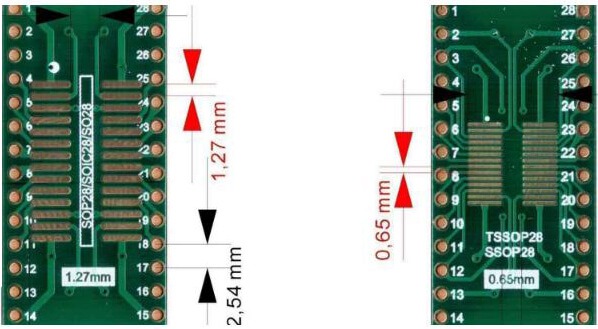
- Microchip: Uses NS suffix = narrow SOIC (150 mil)
- TI: Uses D = standard SOIC (300 mil)
Caution:
Same footprint, different width → won’t fit socket
- Visually identical—but 0806 has a higher voltage rating
- Swapping can cause field failures
- Must be soldered to GND plane
- If left floating → thermal runaway
Pro Tip:
Always check the mechanical drawing in the datasheet—not just the pinout
- Capture: Take a photo and note the package, pins, markings, and location
- Isolate: De-solder if possible—or use in-circuit diode test
- Contextualize: Determine what it’s connected to—Power? Signal? Ground?
- Cross-Reference: Use offline SMD code database and circuit topology
- Verify: Replace with a known-good part; test function—not just resistance
Golden Rule:
If you’re unsure, don’t power the board. A misidentified MOSFET can take down a $200 processor.
Identifying components isn’t about memorizing codes—it’s about thinking like a failure. Every marking, every footprint, every scorch mark tells a story of voltage stress, thermal overload, or supply chain risk.
The best field engineers don’t just read labels—they interrogate the board, question assumptions, and verify before they act.
Because in hardware, a wrong guess doesn’t just waste time—it destroys evidence, burns components, and erodes trust. Know what you’re replacing. Or don’t replace it at all.
When you work with PCBCool, you don’t have to guess. Our expert sourcing, verified components, and PCBA assembly support ensure that every part is genuine, properly rated, and ready for your project—so you can focus on design and troubleshooting without risking burned boards or failed prototypes.