When teams talk about PCB cost reduction, the discussion often starts with unit quantity or supplier geography. While these factors do affect pricing, they are rarely the primary cost drivers. In practice, the final PCB price is largely determined long before a quotation is requested—inside the CAD files themselves.
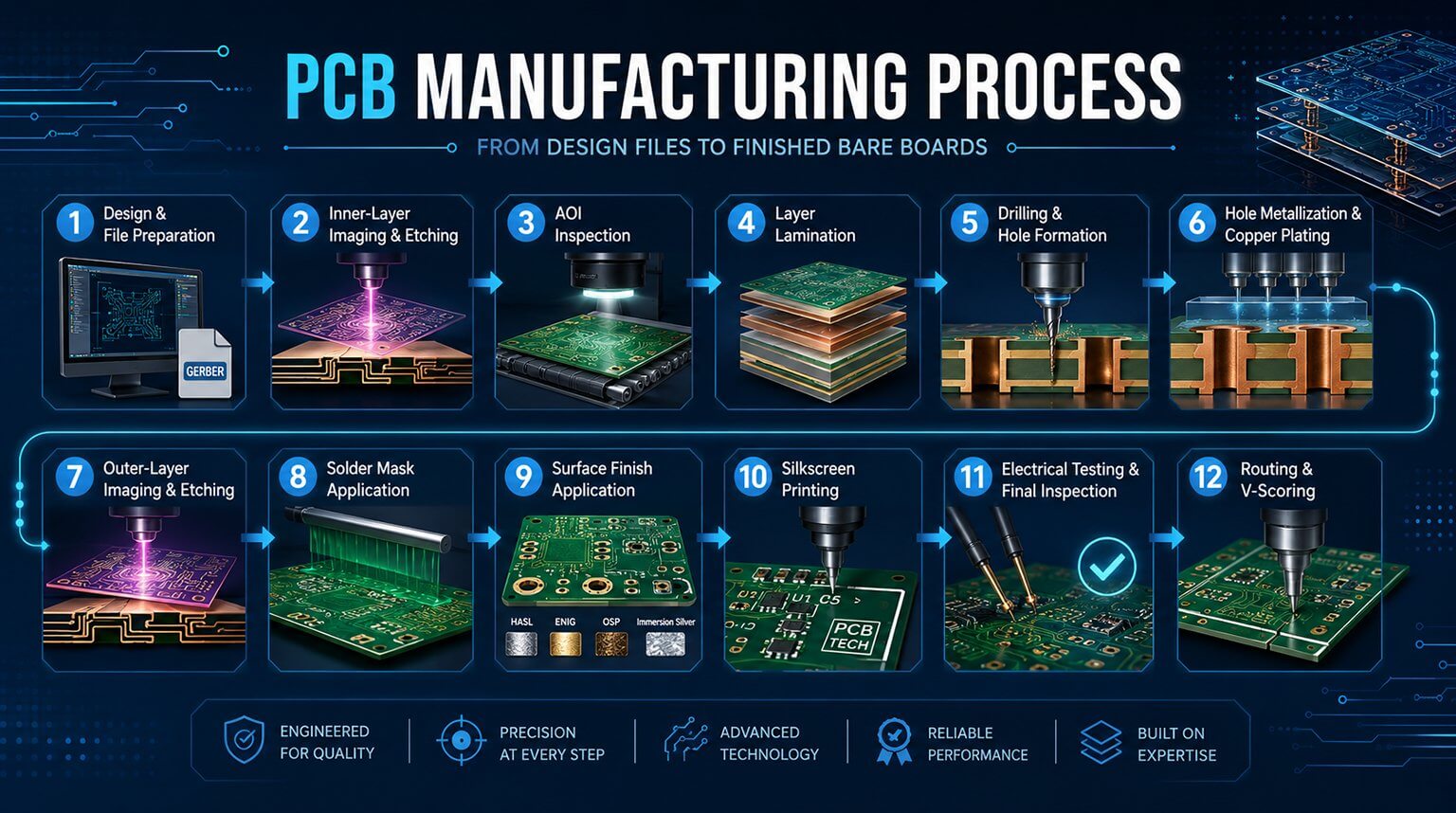
Every design decision made during schematic capture and layout maps directly to a specific fabrication or assembly process. Layer count, material selection, copper weight, trace geometry, via structures, and panel utilization all translate into concrete manufacturing steps. Some of these steps fall well within standard production capability, while others introduce disproportionate cost increases during CAM preparation, fabrication, or assembly.
For hardware startups and engineering teams, reducing PCB cost is not about “cutting corners.” It is about understanding which design requirements genuinely impact electrical performance and reliability—and which ones simply trigger unnecessary cost adders at the factory.
This article approaches PCB cost reduction from a manufacturing-first perspective. By examining how design choices affect both PCB fabrication and assembly, we will outline practical, engineer-approved strategies to lower cost while maintaining yield, reliability, and scalability. The goal is not the cheapest board possible—but the most cost-efficient board that can be built consistently in volume.
FR-4 remains the industry standard because it offers a well-balanced combination of mechanical strength, electrical insulation, and manufacturability. For the vast majority of consumer, industrial, and IoT products, standard FR-4 performs reliably and is the most cost-effective option.
The most important differentiator within FR-4 is glass transition temperature (Tg):
- Standard Tg FR-4 (130–140 °C)
This is the most economical and widely stocked material at fabrication houses. It is fully compatible with standard lead-free reflow profiles and is sufficient for most low- to mid-power electronics.
- High-Tg FR-4 (170 °C and above)
High-Tg materials are necessary only when boards are exposed to sustained high operating temperatures, multiple reflow cycles, or harsh industrial environments. From a manufacturing standpoint, these laminates cost more to source and process, typically adding 15–25% to the bare board cost. Specifying High-Tg “just to be safe” is a common and avoidable cost driver.
Unless your application routinely operates above 130 °C or has demonstrated delamination risk, standard Tg FR-4 is usually the correct—and cheaper—choice.
For RF, microwave, or high-speed digital designs operating in the GHz range, standard FR-4 may introduce unacceptable dielectric loss or impedance instability. In these cases, advanced laminates such as Rogers, Isola, or PTFE-based materials become necessary.
However, the cost impact is substantial. These materials can increase raw laminate cost by 5 to 10 times, and they often require slower processing, tighter controls, and reduced panel utilization at the factory. From a cost-reduction standpoint, high-frequency materials should be limited strictly to layers or regions where their electrical performance is essential, rather than applied board-wide by default.
Board thickness also affects cost more than many designers expect. The industry “sweet spot” is 1.6 mm, which aligns with standard laminate stock, panel fixtures, and automated handling equipment.
Non-standard thicknesses introduce manufacturing friction:
- Ultra-thin boards (≤ 0.4 mm) require special handling during imaging, plating, and chemical processing to prevent warping or breakage.
- Extra-thick boards (≥ 2.4–3.2 mm) often require custom laminate builds and longer drill and plating cycles.
Both cases increase scrap risk and slow throughput, which is reflected in higher pricing. Whenever possible, staying at or near 1.6 mm minimizes these hidden manufacturing penalties.
A 2-layer PCB requires no lamination and follows the simplest manufacturing flow. Once internal layers are introduced, the fabrication process becomes exponentially more complex:
- 4-layer boards require at least one vacuum lamination cycle to bond the inner cores and prepreg.
- 6-layer and above designs typically involve thicker or multiple prepreg sheets, tighter alignment tolerances, and longer press times.
- High-layer-count boards (8+ layers) significantly increase the risk of registration errors, which raises scrap rates and directly impacts unit cost.
From a factory perspective, each lamination cycle is a potential yield loss point. More layers mean more process steps, more opportunities for misalignment, and longer overall cycle time.
High-Density Interconnect (HDI) designs—especially those using Every Layer Interconnect (ELIC)—introduce one of the most expensive processes in PCB fabrication: Sequential Build-Up (SBU).
In SBU, layers are added incrementally through repeated cycles of:
- Lamination
- Laser drilling (microvias)
- Copper plating
Each cycle increases cost, reduces throughput, and tightens process windows. HDI should therefore be treated as a last-resort solution driven by genuine density or signal integrity constraints—not as a default layout choice.
Designers often add layers to resolve routing congestion or improve signal separation. While sometimes necessary, this approach can inflate cost more than expected.
Before increasing layer count, evaluate whether routing optimization can achieve the same goal:
- Reducing trace width and spacing (for example, from 0.15 mm to 0.10 mm) often allows a design to remain at a lower layer count.
- Reorganizing component placement to shorten critical nets can dramatically reduce routing pressure.
- Tightening design rules slightly is almost always cheaper than adding two full layers—provided the fabricator can support the geometry with good yield.
This is where early communication with your PCB manufacturer pays dividends.
Layer count alone is not enough; stackup symmetry plays a critical role in both fabrication stability and assembly yield.
An asymmetrical copper distribution causes uneven thermal expansion during lamination and reflow. This leads to board warpage, which increases the risk of:
- Open solder joints
- Head-in-pillow defects on BGAs
- Automated assembly rejects
As a rule, copper balance should be mirrored across the stackup. For example, on a 6-layer board, a solid copper plane on Layer 2 should be matched with a similar plane on Layer 5. Symmetrical stackups reduce reflow stress, improve flatness, and lower the cost of field failures and rework.
Each drilled hole follows the same mechanical sequence: the spindle moves to position, accelerates to speed, plunges, retracts, and moves to the next coordinate. This cycle repeats thousands of times per panel. As a result:
- A board with 2,000 holes takes an order of magnitude longer to process than one with 200 holes.
- High hole counts reduce panel throughput and become a pricing pressure point, especially in volume production.
From the factory’s perspective, drilling capacity is often the bottleneck that limits daily output.
Most cost-optimized PCB fabricators define a standard minimum mechanical drill size, typically around 0.30 mm. Staying at or above this threshold allows the use of durable, fast-cutting drill bits with high yield.
When drill sizes drop below this limit:
- 0.25–0.20 mm drills require fragile carbide bits
- Feed rates must be reduced to prevent bit breakage
- Tool life decreases sharply, increasing downtime and scrap risk
These factors push the job into a higher pricing tier. Whenever electrical and assembly constraints allow, designing around standard drill sizes is one of the easiest ways to reduce cost.
In addition to hole count, the number of distinct drill sizes affects fabrication efficiency. Each unique drill diameter requires a tool change during the drilling cycle.
- A design using 3–4 via sizes is significantly more efficient to produce than one using 10+ sizes
- Excessive drill size variation increases setup time and lowers overall machine utilization
Reusing via dimensions across power, signal, and ground nets—where feasible—simplifies tooling and improves yield.
Blind and buried vias do not extend through the entire board. While they enable higher routing density, they also multiply manufacturing complexity.
These vias require:
- Drilling and plating of individual layers
- One or more additional lamination cycles
- Tighter registration control
From a cost standpoint, blind and buried vias can easily double the fabrication cost compared to standard through-hole vias. Unless the design is constrained by extreme density (such as smartphone-class layouts), through-hole vias remain the most economical and robust option.
Via-in-pad designs improve routing and signal integrity under fine-pitch components, but they require additional processing:
- Via filling with conductive or non-conductive epoxy
- Planarization
- Copper plating over the filled via
This process typically adds 20–30% to the bare board cost and increases the risk of voiding or solder defects if not tightly controlled. Via-in-pad should therefore be limited to cases where it is functionally required, such as high-pin-count BGAs with tight escape routing.
Hot Air Solder Leveling (HASL) is the most economical surface finish and remains widely used for cost-sensitive designs.
- HASL with lead offers excellent solderability and the lowest processing cost, but its uneven surface makes it unsuitable for fine-pitch components.
- Lead-free HASL is more environmentally compliant but tends to produce “domed” pads due to higher solder surface tension.
From an assembly perspective, HASL’s non-planarity can create challenges for QFNs, fine-pitch QFPs, and BGAs, where pad flatness is critical. HASL is best suited for designs with larger component pitches and relaxed coplanarity requirements.
Electroless Nickel Immersion Gold (ENIG) is widely favored for its flat, uniform surface and long shelf life. It is particularly well-suited for:
- Fine-pitch BGAs and QFNs
- High-reliability assemblies
- Mixed-technology boards requiring consistent solder joints
However, ENIG involves multiple chemical steps and uses real gold, which makes it inherently more expensive. In practice, ENIG typically adds around 10% to the bare board cost compared to HASL. While often justified, it should not be selected by default if the design does not demand its advantages.
Organic Solderability Preservative (OSP) provides a thin organic coating that protects copper until assembly. It offers:
- Excellent pad flatness
- Lower cost than ENIG
- Compatibility with fine-pitch components
The trade-off is shelf life. OSP degrades with handling and exposure, making it best suited for high-volume production where assembly follows fabrication quickly. For startups with tightly coordinated supply chains, OSP can be an effective middle-ground between HASL and ENIG.
Hard gold plating is not a general-purpose surface finish. It is specifically used for edge connectors and gold fingers, such as those on PCIe cards or memory modules.
This process requires:
- Electrolytic plating
- Masking and selective processing
- Manual setup steps
As a result, hard gold introduces significant labor and processing cost. It should be specified only on connector fingers and never across the entire board unless electrically necessary.
Expedited production significantly increases cost because it disrupts factory scheduling and consumes premium capacity.
- A 24-hour quick-turn order can cost 3–4× more than a standard lead time.
- Standard production windows (typically 7–10 working days) allow better panel batching and higher machine utilization.
Whenever possible, plan development timelines to avoid emergency turns. Stable, predictable schedules are one of the simplest cost-reduction levers available to startups.
Fabricators price in expected yield. If a design is likely to produce only 70% usable boards, the cost of the remaining 30% scrap is absorbed into the final quote.
Common yield killers include:
- Overly tight tolerances
- Excessive layer count or HDI features
- Asymmetrical stackups
- Marginal drill sizes and pad geometries
High-yield designs move through the factory faster, generate less scrap, and receive more competitive pricing. In practice, designing for yield is the most powerful long-term cost strategy.
When ordering PCBs, you are not buying individual boards—you are buying real estate on a standard production panel, commonly around 18 × 24 inches.
Fabricators require a 10–15 mm perimeter frame for conveyor handling, fiducials, and tooling holes. What remains is usable panel area. Small changes in board dimensions can have a disproportionate cost impact:
- A layout that fits 6 boards per panel is significantly cheaper than one that fits only 4
- Crossing a panelization threshold can increase per-unit cost by 50% or more
Optimizing board outline early—sometimes by just a few millimeters—can unlock major savings at scale.
Board separation method affects both fabrication speed and downstream assembly.
- V-scoring uses angled blades to score straight lines through the panel. It is fast, highly repeatable, and low-cost.
- Tab routing uses a router bit to cut complex outlines. It is slower, increases tool wear, and consumes more machine time.
Whenever board geometry allows, rectangular boards should be separated using V-scoring. Reserve tab routing for irregular shapes or designs that genuinely require complex outlines.
Reducing PCB cost is not about applying isolated tricks or chasing the lowest quote. It is a systematic process of aligning design intent with manufacturing reality. Every decision—material selection, layer count, via structure, surface finish, panel utilization, and lead time—represents a tradeoff between cost, reliability, and scalability.
While many cost-saving opportunities can be identified through careful PCB design and internal analysis, the most effective improvements often emerge through direct collaboration with the manufacturer. A fabrication partner who understands both engineering constraints and production economics can identify unnecessary cost drivers early—before they turn into yield loss, rework, or delayed schedules.
At PCBCool, our approach is grounded in this philosophy. We focus first on manufacturing quality and process stability, then work with our customers to remove cost where it does not add value.
(You may review a real case study here → [Click Here])
For hardware startups and engineering teams, the goal should not be the cheapest PCB on paper, but the most cost-efficient board that can be built consistently, assembled reliably, and scaled with confidence.