- Client: European Construction Materials Group
- Project: 24VDC / 14A Failsafe Power Control Unit
- Standard: EN 12101-10
In fire safety engineering, people usually worry about the fire. We worry about the gravity.
The client came to us because their previous 350W controller was destroying itself. They had a simple requirement: “Fail-Safe Gravity Deployment.” When the power is cut—whether by a fire alarm trigger or a blackout—the magnetic brake on the motor releases, and the fire curtain drops.
The problem with the old design was physics. The previous manufacturer interpreted “gravity deployment” literally. They just cut the power.
In 2018, we examined the wreckage of a returned unit from a test site in Manchester. The curtain, a heavy steel composite, had free-fallen from a height of 4 meters. Without electronic braking, it hit the floor at roughly 8.8 m/s.
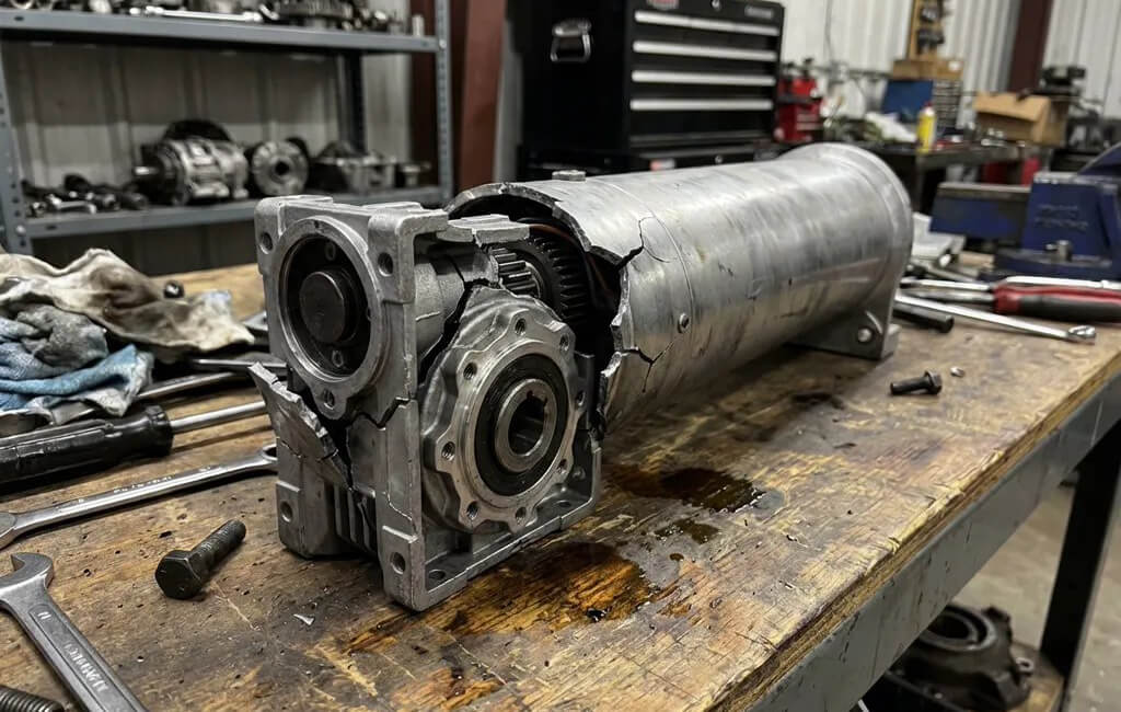
The impact didn’t just make a loud noise; it sheared the M6 bolts holding the limit switches and cracked the gearbox casing of the tubular motor. The curtain was deployed, technically. But the system was total scrap. You can’t ask a building manager to replace a $500 motor every time there’s a false alarm.
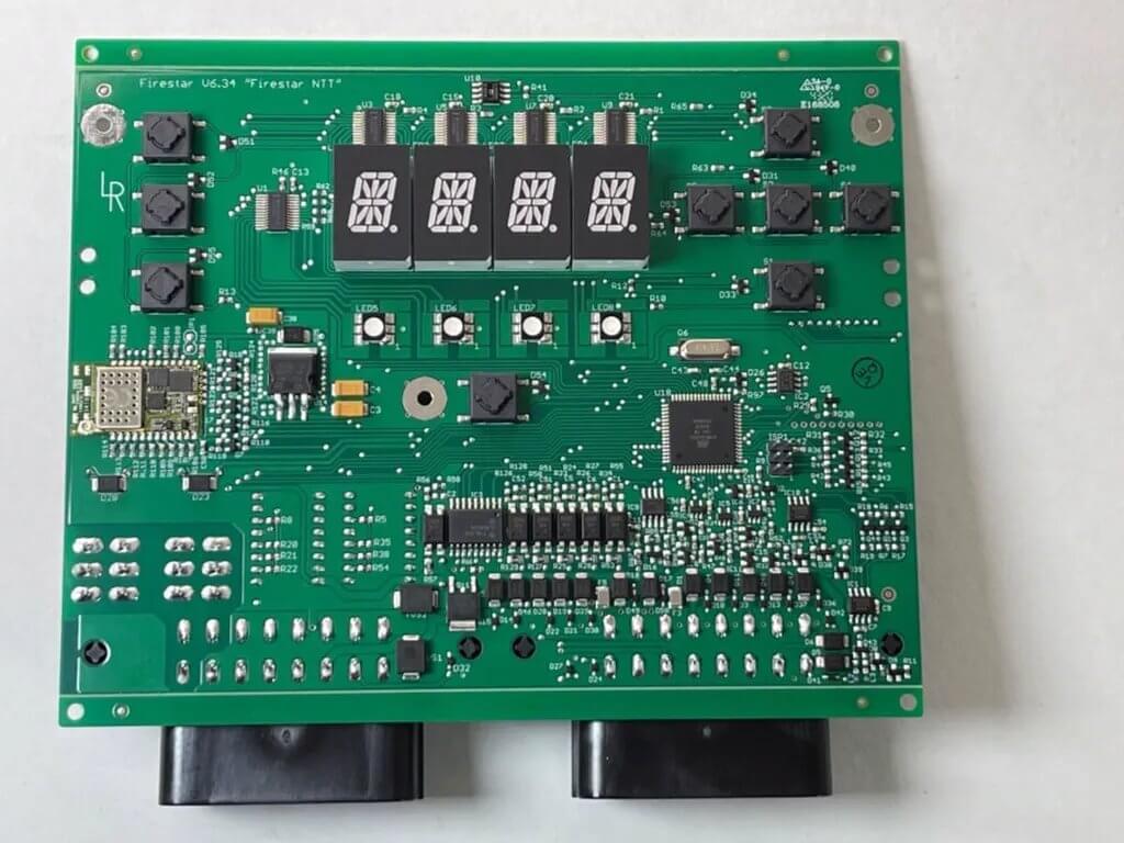
We had to fix this without adding expensive mechanical centrifugal brakes, which would require a redesign of the client’s motor housing. The solution had to be on the PCBA.
We used the motor against itself.
When a DC motor spins without power, it becomes a generator. By creating a closed loop across the motor windings during the descent, we generate a “Back Electromotive Force” (Back-EMF). This force opposes the rotation.
Design Trade-off:
We considered two ways to do this:
- 1. PWM Braking: Use the MCU to pulse the MOSFETs to control speed.
- Pros: Adjustable speed.
- Cons: Requires the MCU to be alive. If the battery dies completely, the brake fails, and the curtain crashes.
- 2. Passive Resistive Braking: Use a relay (Normally Closed) to switch a power resistor across the windings when power is lost.
- Pros: Works even if the PCB is fried. Pure physics.
- Cons: Fixed speed based on resistance value.
We chose Option 2. Reliability wins.
Drafting the Resistance: We needed a descent speed between 0.15 m/s and 0.3 m/s. Now, when power cuts, the relay drops out, the resistor engages, and the curtain floats down gently. No cracked gearboxes.
The interface between the Fire Alarm Control Panel (FACP) and our box is a simple two-wire terminal. The spec says “Voltage Free Contact” (Dry Contact). This means the fire alarm system just closes a switch. No voltage should be sent.
The Reality on Construction Sites
Electricians are tired. They are working in dark basements. They see a terminal block, and they instinctively wire a 24V active signal into it. Sometimes even 110V.
In the previous version, this signal went straight to the MCU GPIO pin.
Result: The MCU exploded.
Return Rate: ~12% of all units were coming back with burnt processors. The client was blaming the installers; the installers were blaming the “cheap electronics.”
The Fix
We stopped trusting the installers. We assumed they would try to kill the board.
We redesigned the input stage using an Omron G2RL-1-E relay combined with an Optocoupler (PC817X).
- If they send a dry contact? The internal logic works as intended.
- If they inject 24V? The optocoupler limits the current. The circuit survives.
- If they inject 110V? The input resistor burns out (sacrificial), but the expensive MCU and the rest of the board are safe. Replacing a $0.05 resistor is better than replacing a $150 mainboard.
The Verification: “The Suicide Test”
We updated the FCT (Functional Circuit Test) matrix. We built a specific fixture that deliberately injects 24VDC into the dry contact port for 5 seconds.
- If the board smokes: Fail.
- If the protection trips but resets: Pass.
The standard EN 12101-10 requires the system to hold standby power for a specific duration (usually 72 hours, but this Class 1 system required 4 hours + 1 cycle due to generator backup).
Many engineers just look at the amps, multiply by hours, and pick the next battery size up. That’s how you get failures in winter.
Here is the actual calculation we used for the DFM report.
Parameters:
- I-standby (Quiescent Current): 80mA (This covers the STM32 MCU in sleep mode, BMS monitoring, and one status LED)
- T-hold (Standby Time): 4 Hours
- I-alarm (Motor Run Current): 12A (Peak start) / 4A (Running) (We use the worst-case 12A for safety)
- T-cycle (Active Time): 0.25 Hours (15 minutes) (Includes multiple retries if the curtain sticks)
The Calculation Draft:
C-required=(I-standby×T-hold)+(I-alarm×T-cycle)
C-required=(0.08A×4h)+(12A×0.25h)
C-required=0.32Ah+3.0Ah=3.32Ah
A 4Ah battery seems enough, right? No.
We have to apply the “Real World Factors”:
- Aging (kage): Lead-acid batteries lose capacity. We assume 80% health after 2 years.
- Temperature (ktemp): These boxes sit in unheated stairwells. At 10°C, capacity drops. We use 0.8.
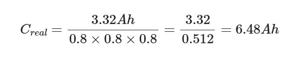
- Depth of Discharge (kdod): You can’t drain a VRLA battery to 0%. We limit discharge to 80% to allow recovery.
Revised Formula:
Selection:
We standardized on Two 12V 7Ah VRLA batteries (Series connection for 24V).
Why VRLA and not Lithium?
Lithium is sexy. It’s also light. But Lithium stops charging at 0°C. VRLA is heavy, cheap, and works when it’s freezing. For a fire safety box that sits in a concrete wall for 5 years, VRLA is still the king.
(Note: We need to verify the brand. We prefer Yuasa, but supply chain issues might force us to generic alternatives. Need to test the internal resistance of the alternates.)
The controller drives a 350W load. The peak current is 14A.
In an open lab bench, 14A is manageable. Inside an IP54 sealed metal box, it’s an oven.
The main heat source is the MOSFET bridge. We use TO-247 packages.
Grease vs. Pads
The previous supplier used silicone thermal pads.
- Pad Thermal Conductivity: ~1.5 W/mK.
- Thickness: 0.5mm.
- Result: During the 14A burn-in test, the MOSFET case temperature hit 105°C. Too close to the limit.
We switched to Dow Corning TC-5026 thermal grease.
- Grease Conductivity: ~2.9 W/mK.
- Thickness: Screen printed to 0.08mm.
- Result: Case temperature dropped to 82°C.
The Torque Problem
Grease is messy. It also requires precise pressure. If you screw the MOSFET down too tight, you squeeze all the grease out and metal touches metal (good for heat, bad if the surface isn’t perfectly flat). If it’s too loose, you have air gaps.
We also found that over-tightening was causing “die stress.”
(Failure record: In Q3 2023, we had 3 units fail after 2 months. Root cause: Micro-cracks in the MOSFET epoxy caused by excessive torque).
Process Update:
We implemented electric screwdrivers (Kilews) preset to 0.6 N·m.
Every single screw torque event is logged in the MES. If the driver detects the screw seated too early (cross-threaded) or too late (stripped), the line stops.
The battery protection logic is critical. If we let the battery drain to 10V, the electronics will shut down chaotically. We need a controlled death.
We set the LVD threshold at 19.5V.
Why 19.5V?
- Nominal Voltage: 24V.
- Fully Discharged (0%): ~21V (under load).
- Deep Discharge Damage zone: < 18V.
We need to cut the power before the battery is destroyed, but after we have squeezed every usable amp out of it.
However, there is a catch. When the load (12A) kicks in, the voltage sags instantly due to internal resistance. We don’t want the LVD to trip just because the motor started.
Logic Adjustment:
We programmed a “debouncing” timer in the firmware.
- If Voltage < 19.5V for > 5 seconds: Cut Power.
- If Voltage dips to 18V for < 1 second (Motor inrush): Ignore.
This prevents nuisance tripping during the weekly self-test.
We don’t do batch testing for this product. Every unit is tested.
| Test Step | Parameter | Purpose / Why we do it |
|---|
| Ground Bond | 25A AC, 60s, <0.1Ω | Standard IEC 62368-1 requirement. If the ground wire is loose, the metal case becomes a shock hazard. |
| LVD Trip | Ramp DC down to 19.5V | Verify the comparator logic works. Tolerance ±0.2V. |
| Back-EMF Load | Simulate motor disconnect | Check if the dump resistor engages. If not, the curtain falls too fast. |
| Full Load Burn-in | 350W, 45°C ambient, 4h | Simulate a summer day in a utility room. |
| Vibration | Random, 10-500Hz | Check if the heavy transformer or battery brackets shake loose. |
This box isn’t smart. It doesn’t use AI. It doesn’t connect to the cloud.
It is a dumb, heavy, robust switch that handles power, gravity, and heat.
The client was initially worried that our solution was more expensive than the previous BOM.
- Relays instead of direct GPIO.
- Branded thermal grease instead of cheap pads.
- Oversized batteries.
But after 18 months of production, the field failure rate dropped from 12% to <0.1%.
The cost of one warranty truck roll to a construction site is about $500. The cost of the extra components was $12.
Sometimes, good engineering is just about spending money on the boring stuff.