This project was created to address a common real-world problem: continuously monitoring indoor environmental conditions without relying on expensive commercial systems. The goal was to develop a compact, low-power, Wi-Fi-enabled monitoring device capable of measuring temperature, humidity, and air quality, and transmitting the data wirelessly for logging and analysis.
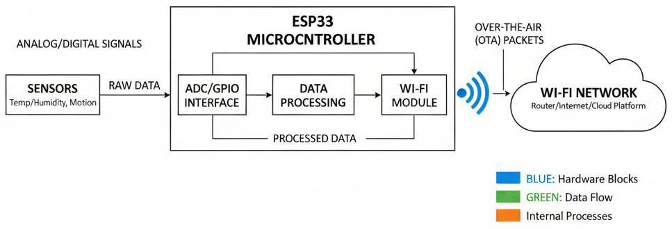
The ESP32 was selected due to its built-in Wi-Fi and Bluetooth capabilities, dual-core processor, strong community support, and suitability for IoT applications. By using the ESP32, the system remains compact and cost-effective, unlike traditional microcontrollers that require external communication modules.
The project was first developed as a functional prototype and later transitioned to a PCB-based implementation, making it suitable for small-scale manufacturing and practical deployment.
Before hardware selection began, the system requirements were clearly defined.
Functional requirements included:
- Periodic measurement of temperature and humidity
- Stable Wi-Fi connectivity
- Serial debugging capability
- Expandability for additional sensors
Non-functional requirements included:
- Low power consumption
- Reliable long-term operation
- Simple firmware structure for easier maintenance
- Easy transition from breadboard to PCB
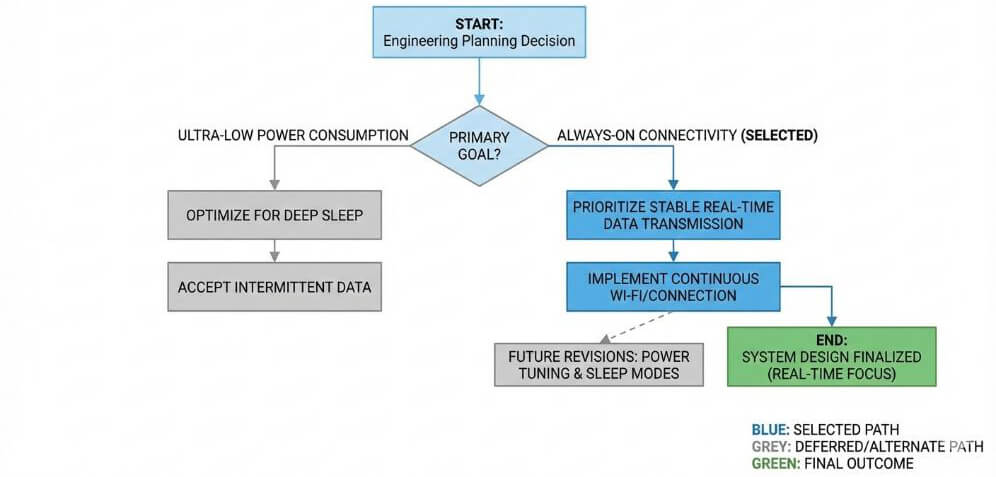
One of the key design decisions during the planning phase was prioritizing continuous connectivity over subsystem power optimization. For this project, stable real-time data transmission was considered more important than aggressive deep-sleep power savings, with power optimization planned for a later revision.
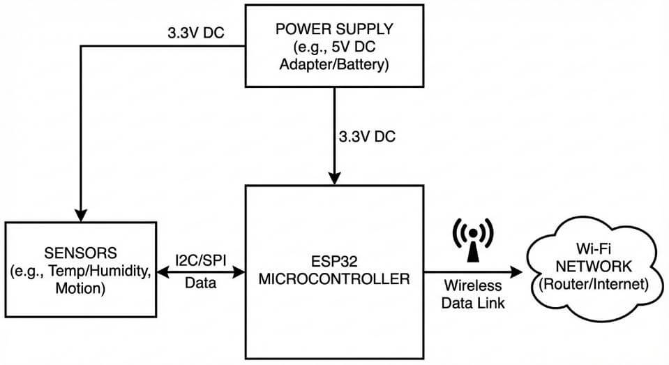
The hardware design was based on an ESP32 development module, selected for its ease of prototyping and wide availability. Digital sensors were used to collect environmental data, and communication over the I²C bus helped reduce GPIO usage and simplify wiring between components.
Key hardware components included:
- ESP32 development module
- Temperature and humidity sensor
- Regulated 5V input with onboard 3.3V regulation
- USB-to-serial interface for programming and debugging
GPIO allocation was planned early in the design phase to avoid conflicts, particularly with pins that affect ESP32 boot modes. Power routing was carefully considered to ensure voltage stability during high Wi-Fi transmission activity, as current spikes during RF operation can otherwise lead to brownouts if not properly managed.
Before transitioning the project to a PCB-based design, the system was first built as a DIY prototype using manual wiring and basic firmware development. This hands-on phase played a critical role in validating both the hardware connections and the core application logic.
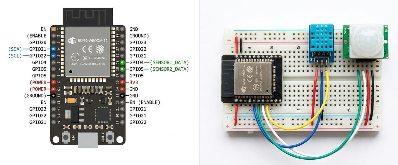
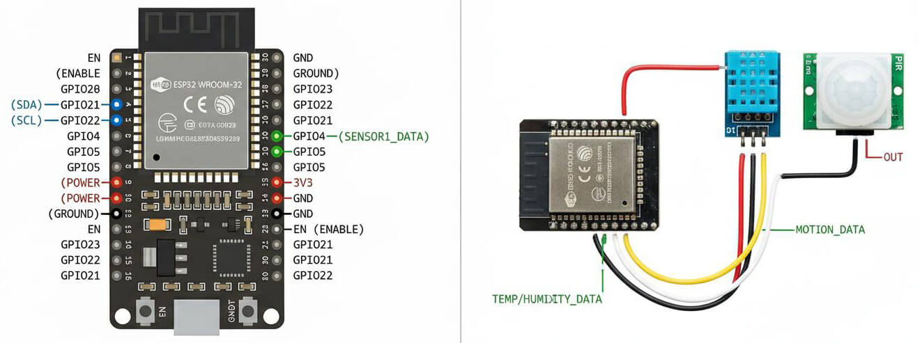
The ESP32 and sensor modules were mounted on a standard breadboard to allow easy access to all GPIO pins during testing. Power was supplied via USB, and jumper wires were used to connect the sensor to the ESP32.
The wiring process followed a simple and repeatable approach:
- ESP32 3.3V pin connected to the sensor VCC
- ESP32 GND connected to the sensor GND
- Sensor SDA connected to the assigned ESP32 GPIO for I²C data
- Sensor SCL connected to the assigned ESP32 GPIO for I²C clock
This visible wiring layout made it easier to identify loose connections, incorrect pin assignments, and power-related issues early in development.
The firmware was developed using the Arduino IDE to keep the project accessible to both hobbyists and professional engineers. Instead of implementing all functionality at once, the code was developed incrementally and tested at each stage.
The development sequence followed this order:
- Uploading a basic ESP32 sketch to confirm successful flashing
- Initializing the sensor library and verifying readings via the serial monitor
- Implementing periodic data acquisition logic
- Adding Wi-Fi connectivity and basic reconnection handling
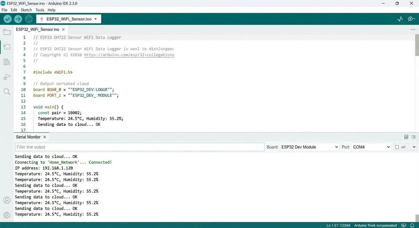
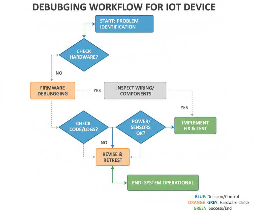
Serial output was used extensively to verify sensor readings, connection status, and overall system stability. This step-by-step approach reduced debugging complexity and ensured that each subsystem functioned correctly before proceeding further.
This DIY wiring and coding phase exposed several issues that would have been more difficult to diagnose on a PCB, including power instability during Wi-Fi transmission and GPIO selection conflicts. Resolving these issues early improved the reliability of the final design and directly informed subsequent PCB layout decisions.
By validating the system through hands-on prototyping, the overall development cycle became more efficient and better prepared for production.
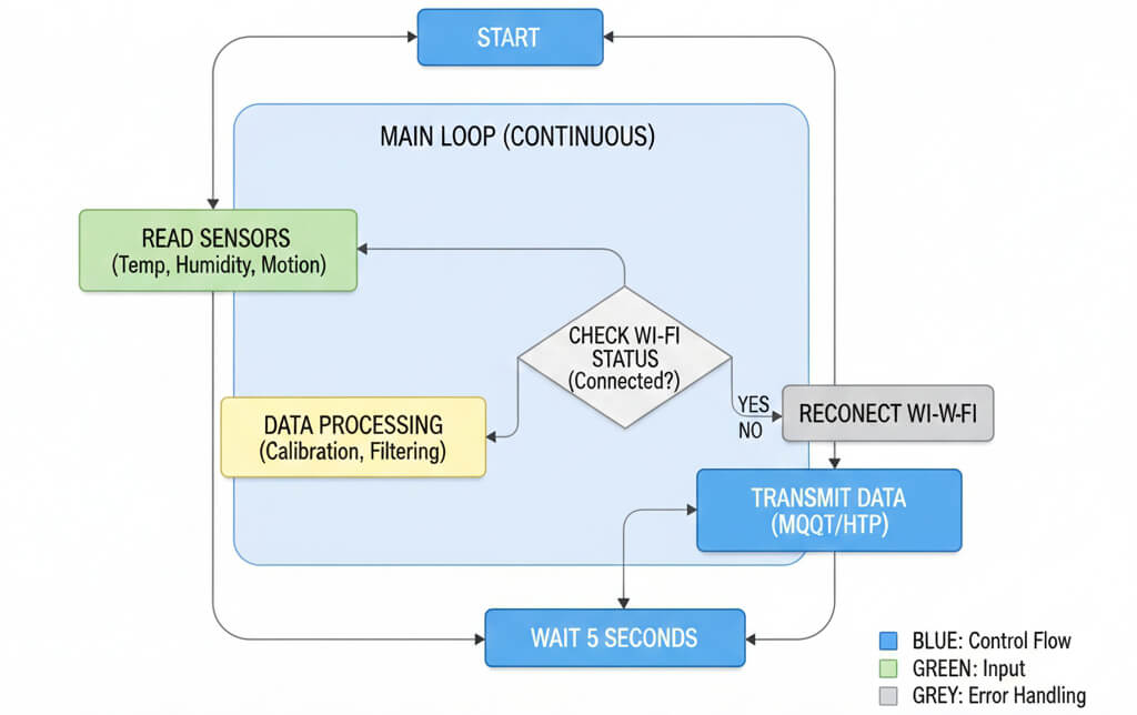
The Arduino IDE was used for firmware development to prioritize code readability and rapid iteration. Rather than implementing all logic within a single main loop, the firmware was structured in a modular manner, separating sensing, data processing, and communication functions.
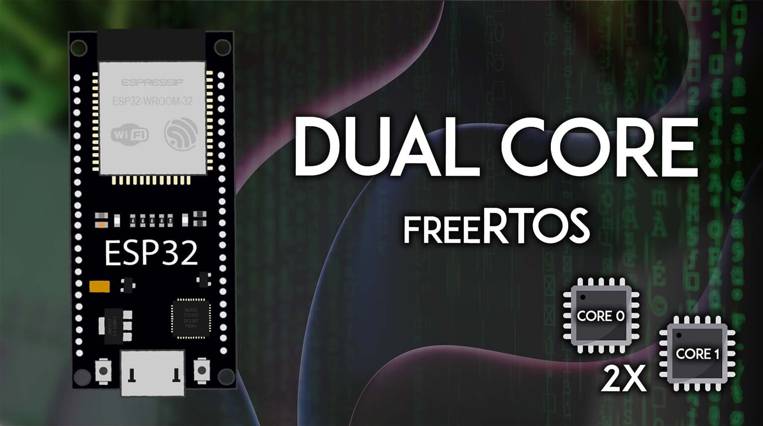
The firmware architecture was designed with the ESP32’s dual-core capability in mind, allowing time-sensitive tasks such as sensor sampling to be conceptually separated from communication-related operations. While this project did not require explicit RTOS task pinning or advanced core management, the overall structure was prepared to support such extensions in future revisions.
Key firmware design principles included:
- Non-blocking delays
- Clear separation between hardware abstraction and application logic
- Serial logging for debugging and validation
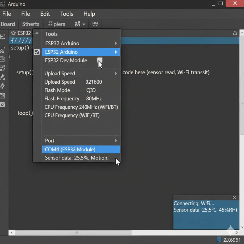
The Arduino IDE was configured with the ESP32 board package, and the appropriate development board was selected. Flash size and upload speed were configured to ensure consistent and reliable firmware flashing.
Serial output was enabled early in the process to verify successful boot behavior and basic system operation before proceeding with sensor integration.
Sensors were connected via the I²C bus, allowing multiple devices to share a common data and clock interface. After wiring, the corresponding sensor libraries were initialized, and raw sensor readings were verified using the serial monitor.
Sensor stability was validated before moving on to network communication to prevent compounded debugging issues later in the development process.
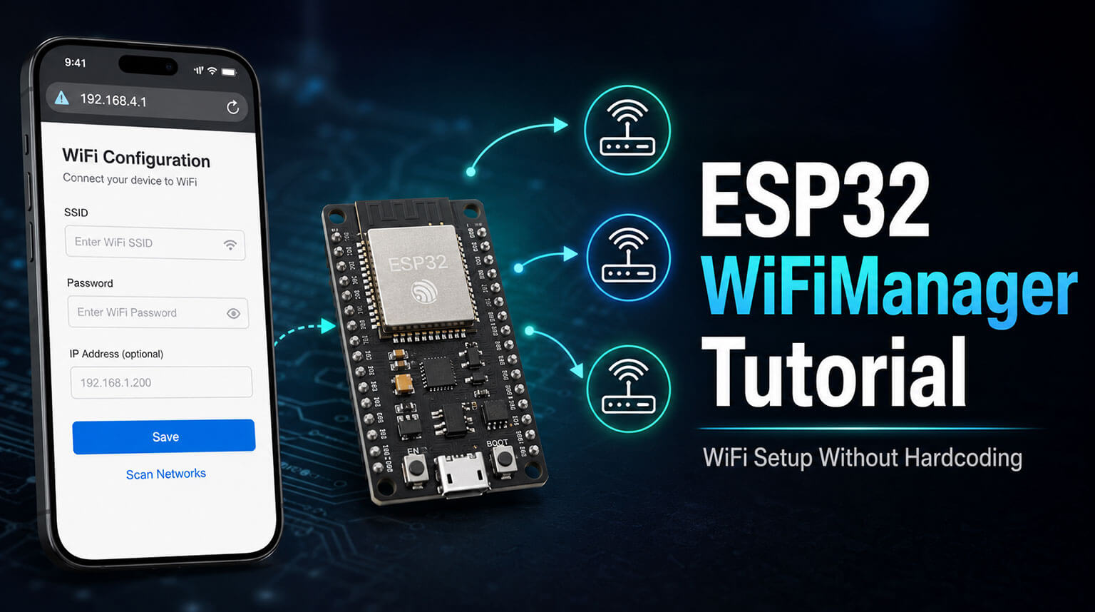
Wi-Fi credentials were handled within the firmware, and connection status was monitored during operation. Once a network connection was established, sensor data was formatted into readable strings for logging or transmission to a remote server.
Basic reconnection logic was implemented to handle temporary network interruptions without causing system crashes or requiring manual resets.
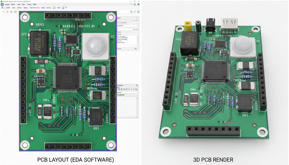
After validating the prototype on a breadboard, the design was transitioned to a simple two-layer PCB. This step significantly improved system stability and reduced electrical noise during initial testing.
Key PCB design considerations included:
- Short power traces
- Proper placement of decoupling capacitors near the ESP32
- Clear separation between power and signal paths
Early PCB planning also helped identify opportunities for GPIO reassignment and improved overall layout efficiency.
Testing was performed in several stages:
- Power stability testing
- Sensor accuracy verification
- Wi-Fi connection stress testing
- Long-duration runtime testing
One significant issue observed during testing was random system resets when the ESP32 was transmitting over Wi-Fi. This behavior was traced to insufficient power buffering and was resolved by adding bulk capacitance near the ESP32 power pins to better handle transient current demands.
The developed system proved effective in collecting reliable environmental data while maintaining stable Wi-Fi connectivity. The final PCB prototype demonstrated improved robustness and was suitable for small-scale production.
This project validated the ESP32 as a capable platform for connected sensing applications where flexibility, performance, and cost are key considerations.
Several lessons emerged from the development process:
- ESP32 power requirements are often underestimated
- GPIO selection has a greater impact than initially expected
- Modular firmware design significantly simplifies debugging
- Transitioning to a PCB earlier helps reduce long-term issues
If the project were to be repeated, greater emphasis would be placed on early power analysis and more forward-looking GPIO planning.
This ESP32 project highlights the importance of structured design, careful power planning, and iterative testing. From the initial concept to a functional PCB prototype, the ESP32 proved to be a capable and flexible platform when supported by sound engineering practices.
For engineers building similar IoT systems, early planning and real-world validation remain critical to long-term reliability. Once a design has been proven on the bench, moving quickly to a well-executed PCB can significantly accelerate development and reduce hidden issues.
Platforms like PCBCool help bridge that gap by streamlining PCB fabrication and prototyping, allowing engineers to focus more on design decisions and system performance rather than manufacturing friction.