The given project was carried out to address a simple yet prevalent indoor issue: poor air circulation due to high temperature and humidity. Ventilation fans in most rooms, particularly in bedrooms, offices, or small laboratories, are usually manually operated. In practice, people often fail to switch them on or off, which results in discomfort and energy loss.
The concept here was to create an automatic room ventilation system that responds to actual environmental conditions. The system continuously monitors temperature and humidity and automatically switches on the ventilation fan. Arduino was chosen because it provides rapid prototyping and reliable sensor integration.
This was not just a demo build. The system was constructed, tested in a real room, tweaked, and then run for extended periods. The following discussion reflects these experimental tests and developments.
The problem was divided into smaller sub-problems before hardware wiring or coding began.
The system needed to:
- Take accurate temperature and humidity readings.
- Determine when ventilation is needed.
- Turn on a high-power fan safely.
- Avoid frequent switching on and off.
A decision was made to use a simple rule-based control strategy instead of complex algorithms. Precision control is less important than achieving stable ventilation.
The final architecture consisted of:
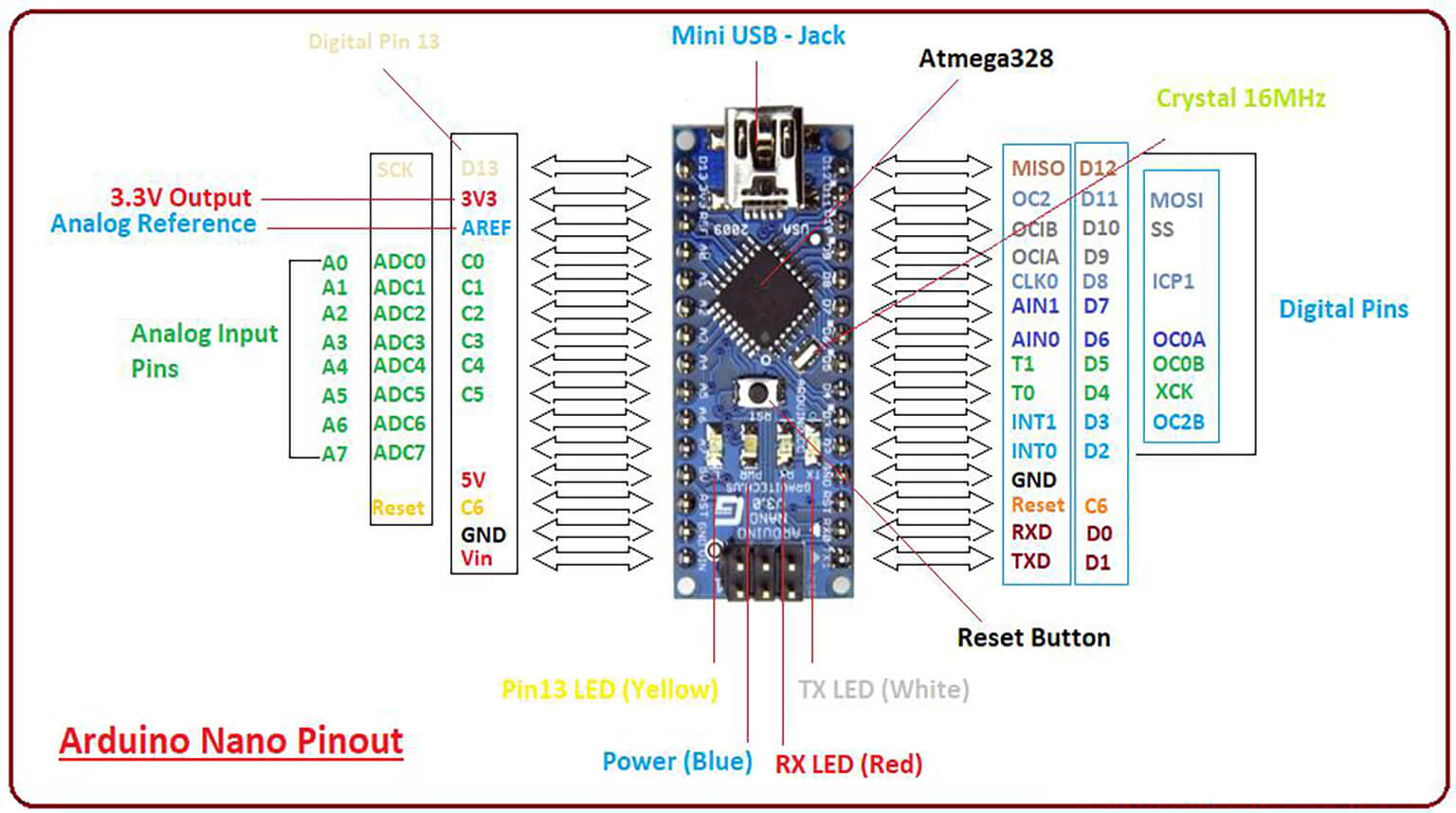
- Arduino Uno as the central controller.
- Temperature and humidity sensor (DHT11).
- Relay module to isolate low-voltage control from high-voltage load.
- Ventilation fan as the output device.
- Keeping sensing, control switching, and power switching independent makes the system safer and easier to debug.
The components used in the project were as follows:
- Arduino Uno
- DHT11 temperature-humidity sensor module
- 5V single-channel relay module
- AC fan controlled via a relay
- Breadboard and jumper wires
- External power supply (used when required by the fan)
The components are all cheap and easily accessible, making this project easy to replicate.
The hardware configuration was kept very simple to minimize wiring errors.
DHT11 Sensor Connection:
- VCC – Arduino 5V
- GND – Arduino GND
- DATA – Arduino digital pin 2
A pull-up resistor was already present in the DHT11 module, so no additional parts were needed.
Relay Module Connection:
- VCC – Arduino 5V
- GND – Arduino GND
- IN – Arduino digital pin 8
The live wire of the fan was connected via the Normally Open (NO) terminal of the relay to ensure that the fan remains off at system startup.
⚠️ Safety precaution: AC wiring was done with care and tested separately before being connected to the Arduino-controlled relay.
The control logic follows a simple flow:
- Read temperature and humidity.
- Compare the values against preset thresholds.
- Switch on the fan when limits are surpassed.
- Switch off the fan when the readings return to normal.
- Wait before taking the next reading.
This logic proved dependable during long-term testing and did not require unnecessary relay switching.
A few minor choices made a tremendous difference in actual application.
The threshold values were initially chosen based on testing. Lower temperatures caused the fan to switch on and off too frequently, so the final value was adjusted to 30 °C.
Second, extensive serial monitoring was conducted during testing. Live monitoring helped confirm the accuracy of the sensor readings and overall system behavior.
Third, care was taken to verify relay behavior. Many relay modules are active-low, which can be confusing for beginners unless tested early.
One of the main challenges was the slow response of the DHT11 sensor. Frequent readings led to duplicated values, which was addressed by introducing longer delays between readings.
Short humidity bursts, such as opening doors or cooking nearby, were another challenge. This was mitigated by using delays and stable threshold values.
Initially, there was noticeable relay clicking noise. Reducing the switching frequency not only decreased the noise but also improved the lifespan of the relays.
This project demonstrated that simple systems are most effective for basic automation. Complicated logic did not improve performance.
It is important to understand the limitations of sensors. The DHT11 is suitable for simple monitoring tasks but not for fast or precise control.
Above all, electrical safety must not be disregarded when handling relays and AC loads.
The next stage of this project may include:
- Replace the DHT11 with a DHT22 sensor
- Add an LCD or OLED display
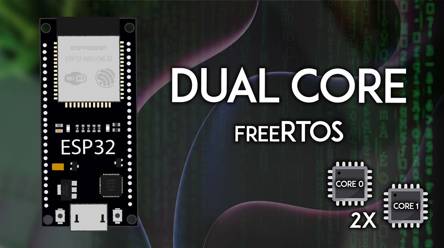
- Enable remote monitoring using an ESP32
- Apply hysteresis for smoother control
This automatic room ventilation system demonstrates how Arduino can use simple logic and hardware to solve real-world problems. Testing, adjustments, and hands-on use helped the project evolve from an idea into a fully functional system.
For beginners, it offers a complete learning experience. For more experienced users, it serves as a reminder that good engineering sometimes lies in keeping things simple, stable, and safe.
For those interested in taking projects from prototype to production, whether as a hobbyist or a business, PCBCool offers flexible PCB and PCBA services. From rapid prototyping to small-batch or full-scale manufacturing, our solutions make it easy to turn ideas into real, working electronics.