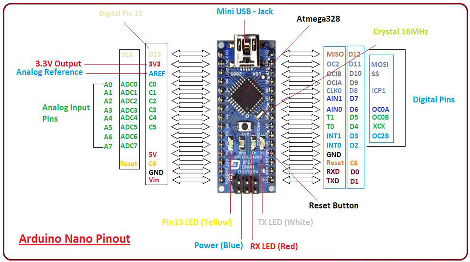
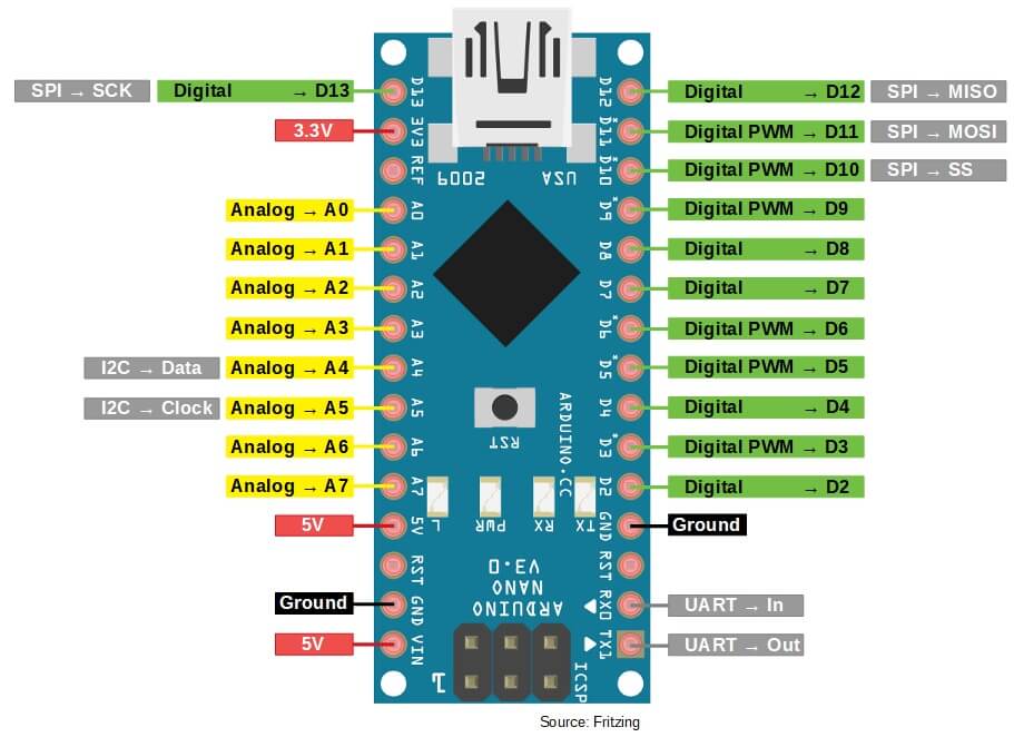
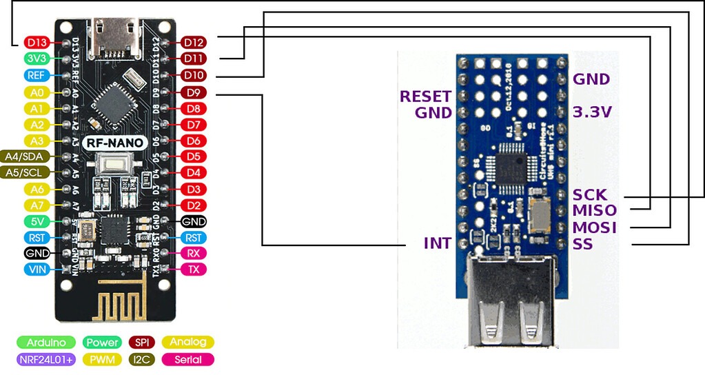
Arduino Nano is miniature, mighty, and versatile—as long as its pins are used correctly according to the Arduino Nano pinout. Novices often try to memorize the pin numbers of the Arduino Nano, but this approach fails in real projects. Problems usually arise when pins don’t behave as expected or when pinout assignments are incorrect, timers are incompatible, or communications fail.
This guide explains how the Arduino Nano pinout functions in real-world scenarios, which pins are reliable, which require special attention, and how engineers actually choose pins when designing a circuit.
The Arduino Nano pinout is centered around the ATmega328P microcontroller, which uses the same core as the Arduino Uno but in a smaller form factor.
Key characteristics:
- 14 digital I/O pins
- 8 analog input pins
- USB programming interface
- Breadboard-friendly and compact design
Because of its small size, careful pinout planning is more critical than on larger boards.
The Arduino Nano has 14 digital pins, D0–D13, but they do not all behave the same. Some pins are general-purpose and safe to use in most applications, while others have special hardware functions that require attention.
General-Purpose Pins
General-purpose pins are simple, predictable, and have no special limitations. They are commonly used for:
Reliable general-purpose pins include D2, D3, D4, D5, D6, and D7. These pins are stable and dependable in the majority of projects.
PWM Pins (D3, D5, D6, D9, D10, D11)
PWM (Pulse Width Modulation) pins are typically used for:
- Motor speed control
- LED brightness control
- Servo control
However, timers may conflict with PWM pins, affecting functions like delay(), millis(), or certain Servo libraries.
Engineering Tip:
Do not use all PWM pins blindly. Plan your pinout assignment carefully based on your project’s requirements.
Pins:
These pins are connected to the USB-to-serial converter.
Common Beginner Mistake
Using sensors with D0 or D1 while also using the Serial Monitor can cause:
- Random data
- Upload failures
- Unstable behavior
Engineering Tip:
Do not use D0 and D1 unless you fully understand serial communication, or your project does not require USB connectivity.
The Arduino Nano has eight analog pins, A0 through A7.
Pins A0–A5
These pins can function as:
- Analog inputs
- Digital pins (D14–D19)
They are commonly used for:
- Potentiometers
- Sensors (gas, light, pressure)
Pins A6 and A7 (Special Case)
Pins A6 and A7 are analog-only and cannot be used as digital pins.
Real-World Issue:
Many beginners try to use A6/A7 with digital sensors and fail.
Important Power Pins:
- VIN – Power input (7–12V recommended)
- 5V – Regulated 5V (output or regulated input)
- 3.3V – 3.3V output with limited current
- GND – Ground
Common Power Mistakes:
- Powering motors directly from the 5V pin
- Supplying 12V directly into the 5V pin
- Ignoring a common ground
These mistakes can cause unexpected reboots, overheating, or permanent damage to the board.
Pins:
Common I2C Devices:
- OLED displays
- RTC modules
- EEPROMs
Engineering Tip:
I2C is reliable, but long wires and poor grounding can cause communication failures. Keep connections as short as possible.
SPI Pins on the Arduino Nano:
- D10 – SS
- D11 – MOSI
- D12 – MISO
- D13 – SCK
Common SPI Devices:
- SD cards
- TFT displays
- High-speed sensors
Engineering Tip:
The onboard LED is connected to D13, which can interfere with SPI timing in sensitive designs.
Based on real project experience, the following pins require extra caution in your Arduino Nano pinout plan:
- D0, D1 – Can conflict with serial communication
- D10–D13 – Potential SPI conflicts
- A6, A7 – Analog-only; cannot be used as digital pins
- 5V pin – Risk of overcurrent
Well-designed circuits avoid using these pins unless necessary.
Pin selection is never arbitrary in real engineering projects. Engineers plan the pinout during the design phase, even before a single wire is connected or a line of code is written.
- Reserve Communication Pins First
Communication pins for UART, I2C, or SPI are limited and highly valuable, so they are allocated early in the design process.
- Allocate PWM Pins Carefully
PWM pins are typically connected to motors, LEDs, or control signals and rely on internal timers. Blind selection of PWM pins can lead to timer conflicts and unreliable behavior.
- Keep Power and Ground Clean
Engineers avoid overloading any single power pin and keep noisy signals away from sensitive analog pins. Proper power pinout management minimizes noise, voltage drops, and inaccurate sensor readings.
Experienced engineers avoid using all available pins. Leaving some pins free allows for future expansion, debugging, or testing without redesigning the circuit.
Novices often run into problems because they choose pins without understanding the Nano pinout and the special functions of certain pins. Common mistakes include:
Beginners may select any free pin without checking if it conflicts with timers, serial communication, or startup behavior.
Internal timers are shared by some pins. Using them together for PWM, delays, or certain libraries can cause timing-based functions to fail.
Connecting too many sensors or modules can lead to voltage drops or board resets.
- Misusing serial pins as general GPIO
Serial pins (D0, D1) are connected to USB or debugging devices. Using them for LEDs or buttons can disrupt programming and serial monitoring.
Many problems that appear as software bugs are actually caused by poor pinout planning.
A typical Arduino Nano project may include sensors, buttons, and a few outputs. A well-organized pinout assignment keeps the project stable and easy to expand.
Preferable for sensors and buttons; general-purpose and do not interfere with communication or uploads.
Used as PWM outputs; can control motors, dim LEDs, or operate actuators. Timer behavior is well-understood.
Suitable for analog sensors like temperature, light, or pressure; kept away from noisy digital signals.
Reserved for I2C communication (displays, RTC modules, or other I2C devices).
Usually not needed in most projects; keeping them free helps avoid upload issues and makes troubleshooting easier.
Learning Arduino Nano pins is not about memorizing numbers or diagrams. It is about understanding the purpose of each pin and using it purposefully:
- Some pins are safe for general use
- Some have special functions
- Others should be avoided in certain situations
Selecting the pinout early and logically during project design makes the system more stable, easier to debug, and simpler to upgrade. Good pinout planning can turn a weak project into a solid one.
For engineers and hobbyists looking to bring their designs to life, PCBCool provides reliable PCB manufacturing and assembly services. With fast turnaround, precise quality control, and expert support, PCBCool makes it easy to turn your Arduino Nano projects into real, working products.