Most consumer wearables fight for attention with bright AMOLED screens. But in the Remote Patient Monitoring (RPM) sector, screens are often a liability. They drain battery power and can confuse elderly users.
A healthcare client needed a tracker that disappears. It had to monitor heart rates, detect falls, and upload data directly to the cloud without needing a smartphone bridge.
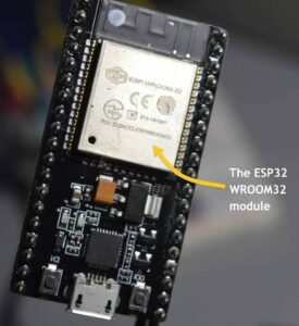
The choice of chip was the ESP32. It offers dual-mode connectivity (WiFi + BLE), which is rare in low-power wearables. But it comes with a penalty: high power consumption.
Here is how the engineering team balanced these constraints.
The ESP32 is a powerful chip, but it wasn’t designed for coin-sized batteries. During WiFi transmission, it pulls over 100mA. With a standard 400mAh battery, the device would die in less than a day.
The mechanical constraints were equally tight. Without a screen assembly to act as a “lid,” the enclosure needed precise molding to stay water-resistant while housing the electronics.
Project Requirements vs. Reality
| Feature | Requirement | Engineering Challenge |
|---|
| Connectivity | WiFi (Cloud) + BLE (Config) | ESP32-PICO-D4 draws high peak current during WiFi TX, complicating power budgeting. |
| Form Factor | Coin-sized, wrist-worn | Mechanical constraints leave no room for a conventional single-layer PCB layout. |
| Battery Life | ≥ 5 days | Default ESP32 idle and sleep currents are too high to meet the target without aggressive power optimization. |
| Sensors | Heart rate + fall detection | Sensors must be electrically isolated from switching noise and RF interference on the PCB. |
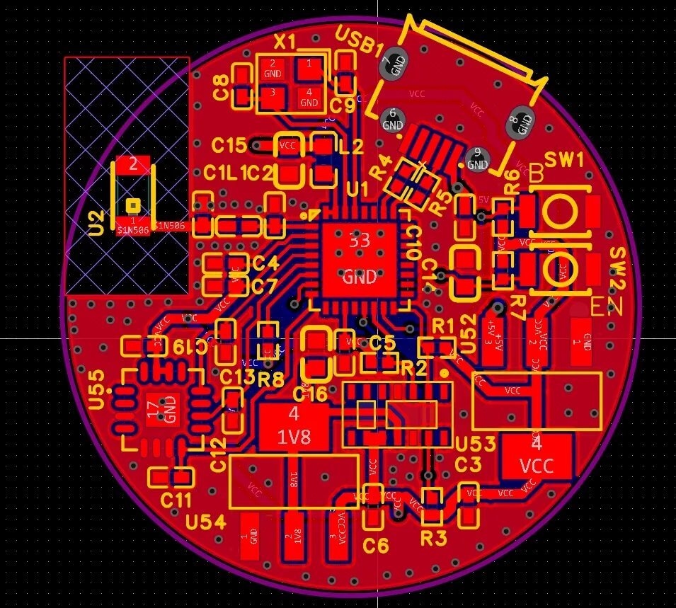
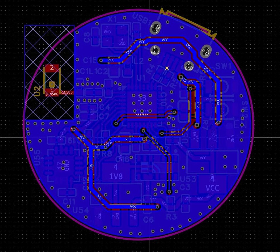
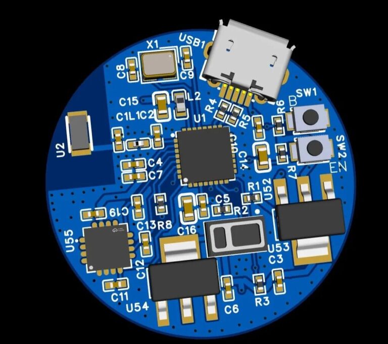
Standard PCB layouts didn’t work. The footprint of the ESP32, battery connector, and sensors exceeded the available area.
The solution was vertical. We implemented a Two-Board Design (Stacked Architecture).
- Mainboard: Holds the ESP32-PICO-D4 and power management circuits.
- Daughterboard: Holds the battery connector, MAX30102 heart rate sensor, and the QMI8658 IMU.
- Connection: A 10-pin FPC (0.5mm pitch) connects the two, folding over to fit inside the curved housing.
To save every millimeter, we used 01005 passive components. This is the limit for many assembly lines, but it was necessary here. We also selected the NCP167AMX330TBG LDO, which comes in a tiny 1mm x 1mm package.
You can’t just put a bigger battery in a watch. The only way to get 5 days of runtime was to change how the system sleeps.
We built a three-tier power architecture:
- Dedicated PMIC: The AXP2101 Power Management IC handles the voltage rails. It’s more efficient than standard LDOs and gives precise control over charging.
- Sensor-Driven Wake: The device stays in Deep Sleep 99% of the time. It doesn’t poll for movement. Instead, the QMI8658 accelerometer is configured to send a hardware interrupt signal only when it detects specific motion patterns (like a fall).
- Pin Holding: We used gpio_deep_sleep_hold_en in the firmware. This keeps specific pins at a defined state during sleep, preventing current leakage without waking the CPU.
RF performance is tricky in screenless devices. There is no glass to let signals pass through easily, and the battery is essentially a block of metal sitting next to the antenna.
We used the ESP32-PICO-D4, which is a SIP (System-in-Package) module. But the matching network still needed adjustment.
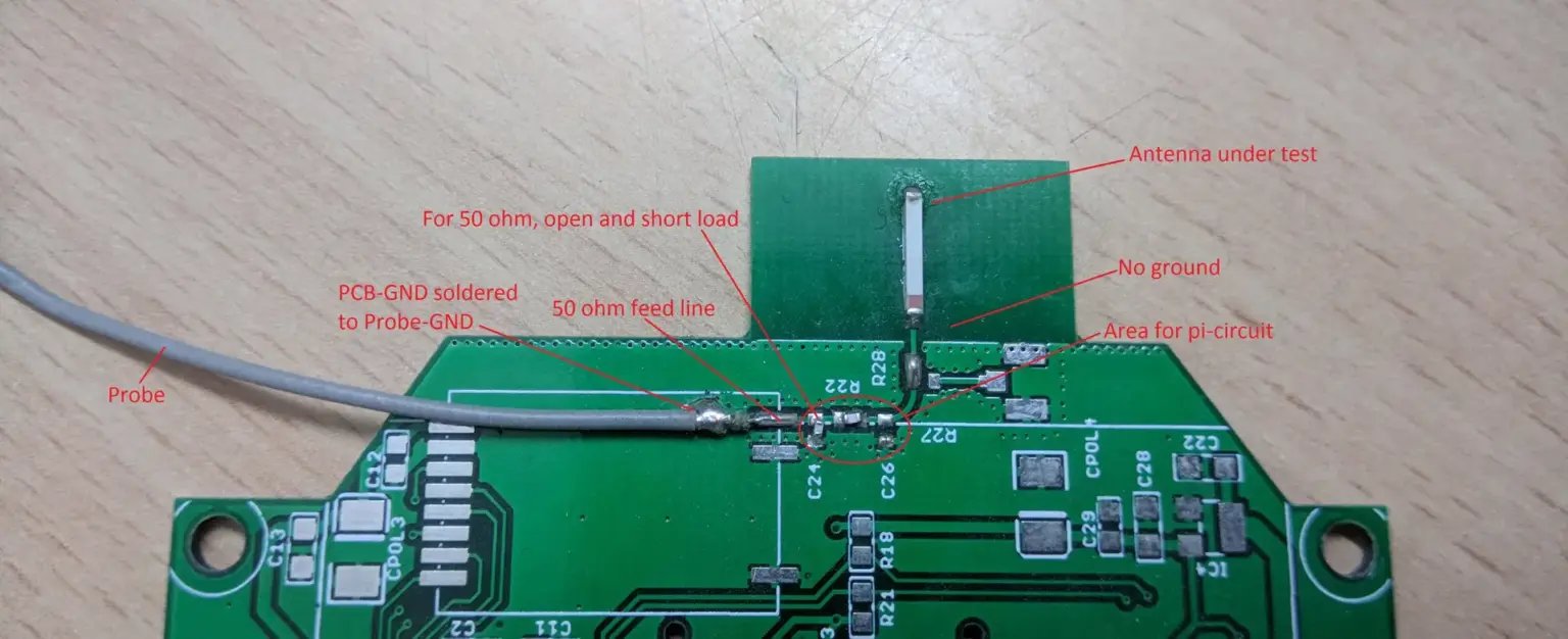
Lab testing showed the body’s proximity detuned the antenna. We adjusted the matching circuit on the PCB to compensate for this, ensuring the device could maintain a stable WiFi connection for bulk data uploads and a BLE 5 connection for initial phone setup.
Building one prototype is different from building 5,000 units. For RPM devices, data reliability is the main metric.
Production Controls:
- FCT (Functional Testing): Every unit goes through a custom test fixture. It simulates heartbeats to verify the MAX30102 sensor and uses a shaker to test the fall detection algorithms.
- X-Ray Inspection: Since the ESP32 and sensors use BGA (Ball Grid Array) packages, visual inspection isn’t enough. X-ray ensures the solder joints underneath are solid.
- Traceability: Medical clients need history. We store test data (RF signal strength, sensor voltage, serial number) for at least 3 years.
This project proves that the ESP32 can be a viable core for wearables if the power management is handled correctly. By using a dual-board architecture and offloading wake-up tasks to low-power sensors, we met the 5-day battery target without sacrificing the dual-mode connectivity.
If you are developing a similar RPM device or screenless tracker, you need to plan for these power and density challenges early in the DFM phase.