Automotive electronics operate under far harsher conditions than typical consumer devices. While smartphones and laptops function in controlled indoor environments and are replaced every few years (typically 2–5 years), automotive PCBs are expected to withstand extreme temperature swings (−40°C to +125°C or higher), continuous vibration, humidity, dust, and electrical noise throughout a vehicle’s lifespan.
In most cases, this means 10–20 years of reliable operation without failure—because in automotive systems, even minor malfunctions can have serious safety implications. Understanding these differences is fundamental to designing PCB that perform reliably in modern vehicles.
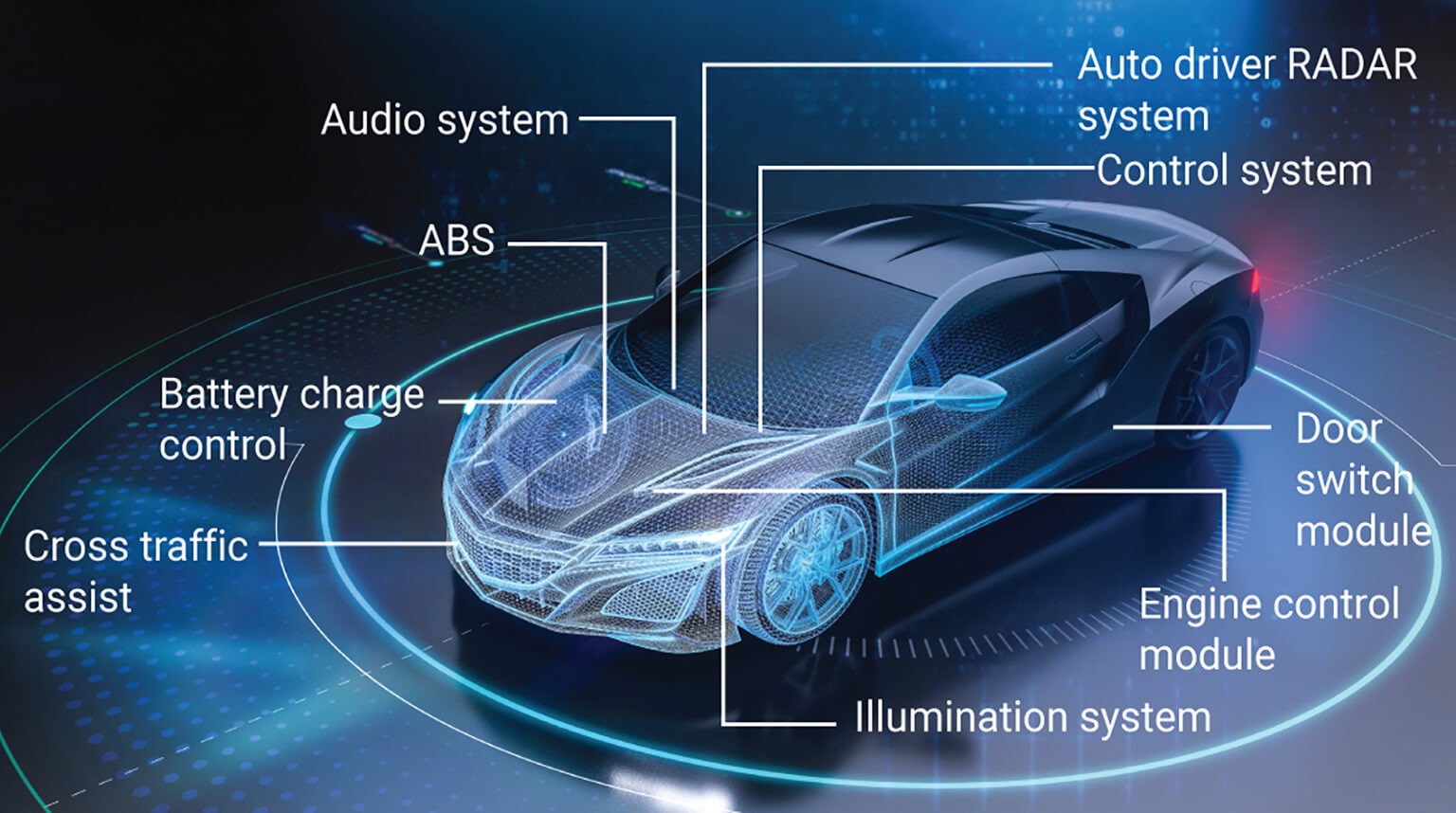
Modern vehicles rely on a wide range of electronic systems, many of which are built around complex PCB assemblies. Key applications include:
- ECU (Engine Control Unit) — controls engine operation, including fuel injection, ignition timing, and emissions
- ADAS modules — support advanced driver-assistance features such as lane keeping, adaptive cruise control, and automatic emergency braking
- Infotainment systems — manage displays, audio, navigation, and in-vehicle connectivity
- Battery Management System (BMS) — monitors and controls battery performance in electric and hybrid vehicles
- Lighting control systems — drive LED headlights, adaptive lighting, and interior/exterior illumination
- Radar and camera modules — enable sensing, imaging, and data fusion for safety and autonomous functions
These applications place strict demands on PCB design:
- High reliability — materials and components must withstand thermal cycling, vibration, humidity, and long-term aging, often meeting AEC-Q100 / AEC-Q101 requirements
- Extended service life — systems are typically expected to operate reliably for 10–20 years
- Functional safety — designs must comply with ISO 26262, ensuring the required Automotive Safety Integrity Level (ASIL) is achieved for safety-critical functions
Standards and certifications are fundamental to automotive PCB design. They ensure that components and systems meet strict requirements for safety, reliability, and long-term performance under harsh operating conditions.
Unlike consumer electronics, failures in automotive systems can have serious safety and legal consequences. For this reason, compliance is not optional—it is required by OEMs, regulators, and supply chain agreements.
The most important standards include:
- AEC-Q100 — Defines stress test qualification for integrated circuits such as microcontrollers and sensors. It includes tests like temperature cycling, high-temperature operating life (HTOL), humidity bias, and electrostatic discharge (ESD). Devices are graded (Grade 0–4), with Grade 0 supporting the highest temperature ranges (up to 150°C).
- AEC-Q101 — Applies to discrete semiconductors such as MOSFETs, diodes, and transistors. It focuses on reliability under thermal, electrical, and mechanical stress conditions typical of automotive environments.
- AEC-Q200 — Covers passive components including resistors, capacitors, and inductors. It evaluates performance under vibration, temperature variation, and mechanical stress to ensure long-term stability.
- ISO 26262 — Governs functional safety for electrical and electronic systems in vehicles. It defines Automotive Safety Integrity Levels (ASIL A–D) and requires hazard analysis, risk assessment, and validation processes for safety-critical systems.
- IATF 16949 — A quality management standard for automotive manufacturing, based on ISO 9001. It emphasizes process control, defect prevention, traceability, and continuous improvement across the supply chain.
In practice, automotive designs rely on components that meet these standards because they are validated for long-term operation under conditions such as wide temperature ranges, vibration, humidity, and electromagnetic interference (EMI). Using non-qualified components increases the risk of early failure and may lead to non-compliance with automotive requirements.
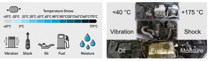
- Standard ambient: −40 °C to +125 °C
- Engine bay / under-hood: up to +150 °C to +175 °C (near exhaust, turbo, or power electronics)
- Rapid thermal cycling and gradients are common.
- Vibration: continuous random vibration (5–2000 Hz, up to 10 g RMS) from engine, road, and drivetrain
- Shock: high-g impacts (e.g., potholes, crashes) — typically 50–100 g for milliseconds
- Road impact & flexure: repeated bending and torsion on boards and solder joints
- Engine oil, transmission fluid, and brake fluid
- Fuels such as gasoline, diesel, and ethanol blends
- Coolants (typically glycol-based)
- Road salt, cleaning agents, and other contaminants
These conditions often require the use of conformal coatings, chemically resistant solder masks, and carefully selected materials.
- High humidity levels (often approaching 95% RH) combined with temperature cycling
- Condensation forming inside enclosures due to thermal gradients
- Potential water ingress from rain, washing, or harsh environments
Designs typically address these risks through proper sealing strategies and, where necessary, pressure-equalizing or breathable vents to reduce condensation buildup.
Automotive enclosures are commonly specified using Ingress Protection (IP) ratings, which define resistance to dust and water:
- IP54 — protection against dust ingress and water splashes
- IP67 — dust-tight and protected against temporary immersion
- IP69K — designed for high-pressure, high-temperature washdown environments
The required rating depends on the application and mounting location of the electronics.
These environmental factors directly influence material selection, PCB stack-up, and mechanical design. In practice, automotive designs often incorporate features such as thicker copper layers, reinforced vias, protective coatings, and validation testing (e.g., thermal cycling and vibration) to ensure long-term reliability.
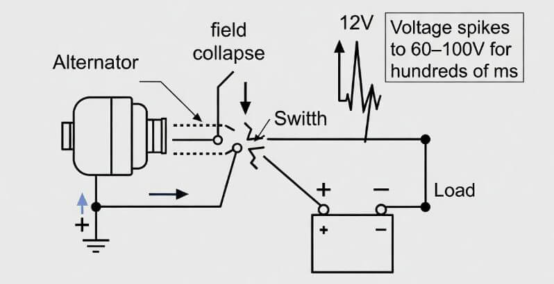
- Passenger cars: 12 V nominal (battery ~12.6 V charged, alternator ~13.5–14.5 V)
- Heavy trucks & commercial vehicles: 24 V nominal (two 12 V batteries in series)
- Load dump — sudden disconnection of a high-load (e.g., alternator field collapse when battery disconnects while charging). Voltage spikes to 60–100 V (or higher unsuppressed) for hundreds of ms.
- Cold crank — Battery voltage drops severely during engine start in low temperatures (thick oil, weak battery). Can sag to ~3–6 V for tens to hundreds of ms.
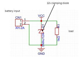
To survive these extremes, input protection circuits are mandatory:
- TVS diodes (Transient Voltage Suppressors) — Clamp high-voltage spikes (e.g., load dump) by avalanching above a breakdown voltage, shunting energy to ground. Placed across power lines.
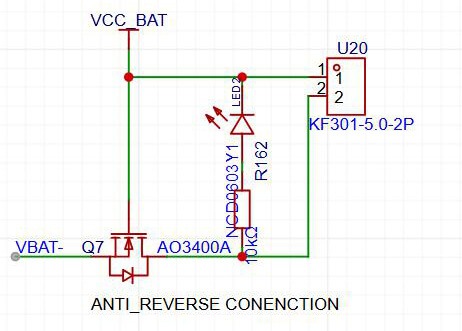
- Reverse polarity protection — Prevents damage if battery cables are connected backwards. Common methods: series diode (simple but lossy), P-channel MOSFET (low loss, ideal for high current).
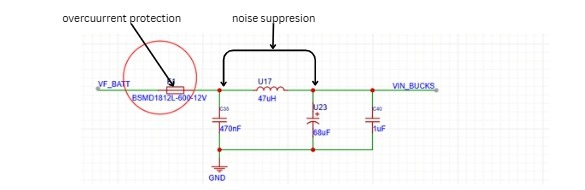
- Surge suppression — Additional elements like fuses, varistors, or LC filters to handle inductive kicks, ESD, and noise.
- CISPR 25 — Defines limits for conducted and radiated emissions from automotive components. It is primarily intended to protect onboard receivers such as radio, GNSS, and wireless communication systems.
- ISO 11452 — Specifies immunity test methods for electronic modules exposed to radiated electromagnetic fields, ensuring reliable operation in the presence of external interference sources.
- Additional related standards — ISO 7637 (electrical transients on supply lines) and ISO 10605 (electrostatic discharge immunity).
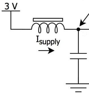
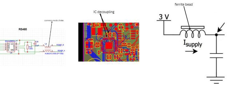
- Input filtering — LC filters, π-filters, or ferrite + capacitor combinations at power entry to block high-frequency noise from entering or leaving the board.
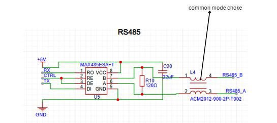
- Common-mode chokes — Placed on power and signal lines to suppress common-mode currents that cause cable radiation.
- Abschirmung — Metal cans over noisy sections (e.g., switching regulators, high-speed interfaces), or full-board shields for sensitive RF modules.
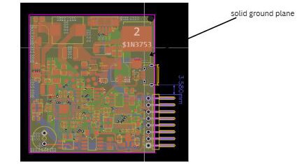
- Ground planes — Solid, unbroken ground planes (multi-layer preferred) to provide low-impedance return paths and reduce loop areas.
- Ferrite beads — Series elements on power rails, clock lines, and I/O to attenuate high-frequency noise.
- Cable emissions — Twisted pairs, shielded cables, proper connector grounding to minimize radiation from harnesses.
- Short return paths — Minimize loop area for high di/dt currents (switching nodes, fast edges). Route return currents directly under signals on adjacent layers.
- Star grounding — Single-point ground reference for analog/digital sections to avoid ground loops; separate analog, digital, and power grounds, connect at one point near power entry.
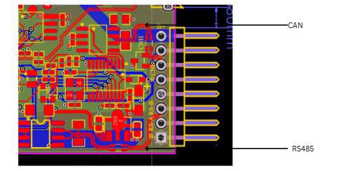
- Partition noisy vs sensitive circuits — physically separate high-noise areas (DC-DC converters, motor drivers, CAN transceivers) from sensitive analog/RF sections; use moats, split planes, or guard traces if needed.
EMC is verified late in development via chamber testing, so early design choices (component selection, layer stackup, filtering) are crucial to avoid expensive respins
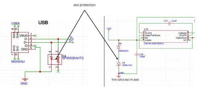
Automotive systems can encounter ESD from human contact, machines, or charged devices. Standards include:
- Human Body Model (HBM)
- Machine Model (MM)
- Charged Device Model (CDM)
- Vehicle-Level ISO 10605
Key design practices:
- Protect all exposed pins (connectors, switches, test points) with dedicated ESD diodes or TVS arrays (bidirectional, low capacitance for high-speed lines).
- Place as close as possible to the connector; use ground planes and short paths to shunt current.
EFTs typically arise from rapid switching of inductive loads, generating repetitive high-speed pulses (5 ns rise, 50 ns width, up to ±150 V). ISO 7637-2 specifies standardized test pulses, such as Pulse 3a/3b.
Mitigation strategies:
- Low-ESR ceramic capacitors close to ICs
- Common-mode chokes on power lines
- Ferrite beads
- TVS diodes rated for repetitive transients
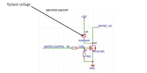
When relays, solenoids, or motors are switched off, inductive components can produce high-voltage spikes (flyback voltage). ISO 7637-2 defines negative and positive pulses (e.g., Pulse 1 and Pulse 2a).
Protection techniques:
- Freewheeling (flyback) diode across inductive load
- Bidirectional TVS across power lines
- Route CAN-FD, FlexRay, and Automotive Ethernet as tightly coupled differential pairs.
- Constant spacing, no length mismatches >0.1–0.2 mm for high-speed.
- Keep pairs away from noisy traces (power switching, clocks); use ground planes underneath for reference.
- Avoid vias on differential pairs when possible — or use matched via pairs if unavoidable.
Critical for high-speed buses, typical target impedances:
- CAN-FD/FlexRay: 120 Ω differential
- 100BASE-T1: 100 Ω differential
Use stackup calculators to set trace width, spacing, dielectric thickness, and copper weight. Maintain ±10% tolerance (tighter ±5% for Ethernet); verify with TDR (time-domain reflectometry) during prototype testing.
- CAN/CAN-FD: 120 Ω resistors at physical ends of the bus (split termination with capacitors to ground for common-mode filtering is common).
- FlexRay: 100 Ω differential termination per channel.
- Automotive Ethernet: Integrated PHY termination (no external resistors needed on board for most 100BASE-T1 PHYs), but ensure trace impedance matches cable/connector. Place termination components close to connectors or last nodes; avoid stubs.
Automotive electronics are evolving rapidly, driven by electrification, connectivity, and advanced driver assistance systems. As vehicles become more complex and safety-critical, PCB design plays an increasingly important role in ensuring system reliability and performance.
Bei PCBCool, we support automotive PCB projects end-to-end, including design optimization, fabrication, and assembly. Our team is experienced in handling automotive-grade requirements, from material selection and stack-up design to EMC-focused layout and reliable manufacturing processes.
If you are working on an automotive project, we’re ready to help you move from concept to production with confidence.