When engineers evaluate PCB performance, the conversation usually centers on routing density, impedance control, stack-up design, EMI mitigation, and thermal management. The substrate material, by contrast, is often treated as a default choice rather than an active engineering variable.
That assumption works for many ordinary boards. It breaks down much faster in high-speed digital designs, RF circuits, power electronics, automotive control systems, and aerospace hardware. In those applications, the substrate is not just supporting copper. It directly affects insertion loss, signal integrity, via reliability, thermal cycling performance, moisture sensitivity, and long-term dimensional stability.
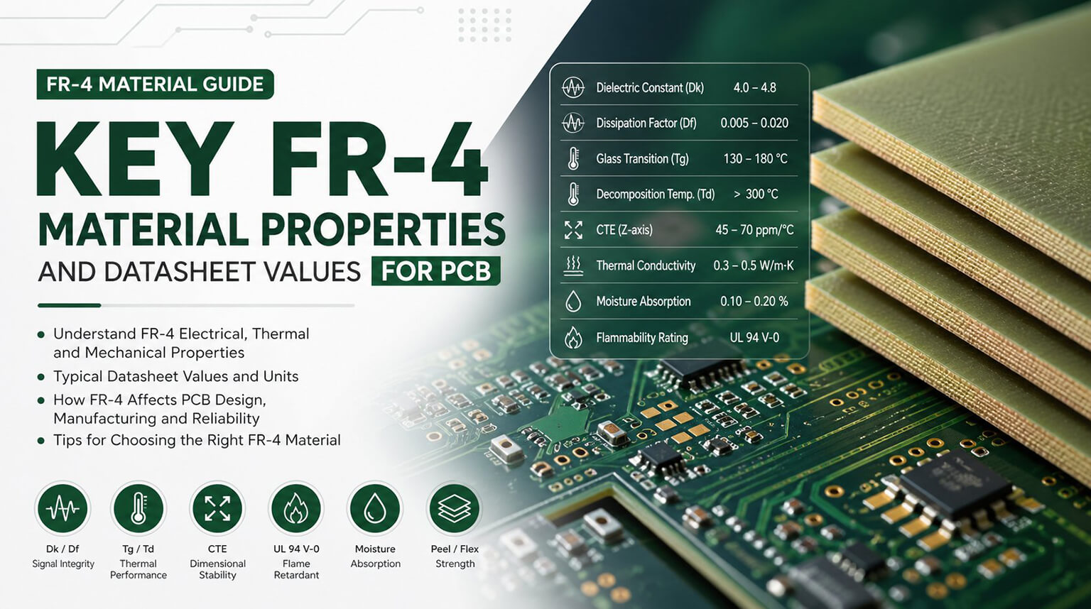
That is why substrate selection should be based on measurable material properties, not broad labels like “low loss” or “high-temperature resistant.” The real engineering conversation starts with numbers: dielectric constant, dissipation factor, glass transition temperature, decomposition temperature, coefficient of thermal expansion, thermal conductivity, and moisture absorption.
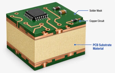
The easiest way to understand a PCB substrate is to think of it as the board’s foundation. It is the solid, insulating base underneath the copper circuit—the part that gives the PCB its body and keeps the conductive layers from touching each other.
If you cut a PCB open and look at its structure, the substrate is the main non-metal material inside the board. In a standard rigid PCB, that material is usually a glass-reinforced epoxy laminate such as FR-4. In other types of boards, it may be PTFE, polyimide, ceramic, or a dielectric layer bonded to a metal core.
So when people talk about PCB substrate materials, they are not talking about the copper foil, solder mask, or surface finish. They are talking about the main insulating material that the circuit is built on.
- Dielectric Constant (Dk):
Affects signal propagation speed and impedance. Lower Dk generally supports faster signal travel, while tighter Dk control helps maintain predictable impedance in controlled traces, differential pairs, and RF structures.
Reflects how much electrical energy is lost as heat inside the dielectric. This becomes more important as frequency and data rate increase. Higher Df means higher dielectric loss, which shows up as increased insertion loss and reduced signal integrity margin.
- Glass Transition Temperature (Tg):
Marks the temperature range where the resin system begins to soften and mechanical behavior changes. Below Tg, the material stays comparatively stable. Above Tg, expansion increases faster and dimensional stability worsens.
- Decomposition Temperature (Td):
Is the upper thermal survival limit, the point at which the material begins to chemically break down. This matters in multilayer fabrication, lead-free assembly, and any process that pushes the laminate hard thermally.
- Coefficient of Thermal Expansion (CTE):
Matters because excessive Z-axis expansion puts stress on plated through-holes, vias, and internal copper structures. In reliability work, this is often where seemingly acceptable materials start to fail.
Becomes critical when the board has concentrated heat sources. Standard substrate materials move heat poorly compared with metal-core or ceramic systems.
Affects insulation resistance, dielectric behavior, dimensional stability, and assembly reliability. Lower moisture absorption is usually preferred in high-frequency and high-reliability environments because it helps keep electrical behavior more stable.
FR-4 remains the most widely used PCB substrate in commercial electronics. It is a woven glass-reinforced epoxy laminate that offers a practical balance of electrical insulation, mechanical strength, manufacturability, and cost.
In electrical terms, FR-4 is a general-purpose dielectric material, typically with a dielectric constant in the range of 4.2 to 4.8 at 1 GHz. Its dissipation factor is commonly around 0.015 to 0.025 at the same frequency, which is acceptable for many conventional digital designs. As frequencies move into the multi-gigahertz range, however, FR-4 dielectric loss becomes more significant, increasing insertion loss in longer traces, backplanes, and other loss-sensitive interconnects.
Standard FR-4 typically has a glass transition temperature (Tg) of about 130°C to 140°C. Once the material moves above Tg, the resin system begins to soften, and Z-axis expansion increases sharply. Below Tg, the Z-axis coefficient of thermal expansion (CTE) is often around 50 to 70 ppm/°C; above Tg, it can exceed 200 ppm/°C.
FR-4 also has relatively low thermal conductivity, usually around 0.25 to 0.30 W/m·K, so it is not well suited to designs that need efficient heat spreading through the base material. Moisture absorption is another consideration. Depending on the formulation, FR-4 can absorb around 0.10% to 0.20% moisture, which can affect insulation resistance and slightly alter dielectric behavior in humid operating environments.
High-Tg FR-4 is designed primarily for improved thermal reliability rather than dramatically different electrical performance. In many cases, its dielectric constant and dissipation factor remain broadly similar to those of standard FR-4, with typical dielectric constant values around 4.1 to 4.6 at 1 GHz and dissipation factor values around 0.014 to 0.020.
The main difference lies in thermal behavior. High-Tg FR-4 typically has a glass transition temperature in the range of 170°C to 180°C, compared with roughly 130°C for standard FR-4. Its decomposition temperature is also higher, often exceeding 330°C. Because the onset of rapid Z-axis expansion occurs at a higher temperature, the material remains dimensionally stable through a greater portion of the reflow and thermal cycling profile.
That improved stability helps reduce mechanical stress on plated vias and internal copper structures during lead-free assembly and repeated thermal cycling. Many high-Tg FR-4 grades also offer relatively low moisture absorption, which further supports reliability in demanding operating environments.
CEM materials, especially CEM-1 and CEM-3, are composite epoxy-based laminates used in cost-sensitive applications where performance requirements are more modest. Of the two, CEM-3 is more relevant to modern double-sided boards because it offers characteristics broadly similar to FR-4 while still serving lower-cost products.
One representative CEM-3 shows permittivity around 5.1 at 1 MHz, dissipation factor around 0.020, moisture absorption around 0.09%, Tg around 135°C, and Td around 310°C. Those numbers make it usable for general electronics, but they also make its limitations clear. It is not built for high-frequency, low-loss, or thermally demanding designs.
Rogers laminates are widely used in RF, microwave, and other high-frequency designs where standard materials’ dielectric loss and looser electrical behavior are no longer acceptable.
For example, RT/duroid 5880 is commonly cited for low-loss microwave work. According to the values, it has a dielectric constant of about 2.20 at 10 GHz, a dissipation factor of about 0.0009 at 10 GHz, moisture absorption of about 0.02%, and thermal conductivity around 0.20 W/m·K.
The tradeoff is cost, and in some PTFE-based systems, more fabrication attention is still required. Rogers materials are chosen when electrical predictability and low loss justify the extra expense.
Polyimide is a high-performance substrate material used in flexible circuits, rigid-flex constructions, and certain rigid PCB applications that require strong thermal durability and long-term reliability.
Electrically, polyimide typically has a dielectric constant in the range of about 3.2 to 3.6 at 1 GHz, with a dissipation factor of roughly 0.008 to 0.015, depending on the specific formulation. Its thermal properties are one of its main advantages: glass transition temperatures can exceed 250°C, and decomposition temperatures may exceed 400°C.
Polyimide also offers relatively low Z-axis coefficient of thermal expansion, often around 40 to 55 ppm/°C. That helps improve dimensional stability under thermal stress and can support better reliability in structures exposed to repeated temperature cycling.
Moisture absorption is an important consideration. Polyimide materials can absorb roughly 0.20% to 0.40% moisture, so controlled storage is important, and pre-baking is often recommended before assembly when moisture exposure has been significant.
Metal-core substrates, most commonly aluminum-core and sometimes copper-core constructions, are used when thermal management is more important than high-speed electrical performance. In these structures, the copper circuit layer is bonded to a metal base through a thin dielectric layer, allowing heat to move more efficiently into the base metal than it would through a conventional stack-up.
The actual electrical and thermal properties of a metal-core PCB depend heavily on the dielectric layer rather than the metal plate alone. In one published Thermal Clad example, the dielectric system is listed with product thermal conductivity of 4.1 W/m·K, dielectric thermal conductivity of 2.2 W/m·K, dielectric constant of 7, Tg of 150°C, and decomposition temperature up to 420°C at 5% weight loss. The same datasheet emphasizes low thermal impedance and use on aluminum or copper base substrates.
For this reason, metal-core PCBs are typically chosen for LED lighting, power conversion, solid-state relays, automotive lighting, and other high-power-density products where rapid heat spreading is a primary design requirement.
In PCB and electronic packaging work, the most common ceramic systems include alumina (Al2O3) and aluminum nitride (AlN), with alumina generally offering a more economical balance and AlN being selected when heat dissipation requirements are significantly higher.
Published Kyocera material data shows alumina substrates with dielectric constant around 9.9 at 1 MHz and thermal conductivity commonly in the range of about 29 to 34 W/m·K depending on grade. Aluminum nitride, by comparison, shows thermal conductivity around 150 W/m·K in one grade set, dielectric constant around 8.5 to 8.6 at 1 MHz, and zero water absorption in the referenced material table. Kyocera also publishes a high-reflectivity alumina substrate for LED applications with thermal conductivity of 19 W/m·K.
Because of these characteristics, ceramic substrates are widely used in power modules, LED packages, RF power circuits, semiconductor packaging, automotive electronics, and other systems where standard organic laminates cannot provide enough thermal or dimensional stability.
Standard laminate materials sufficiently meet the electrical performance requirements for applications below 1 GHz with impedance tolerance greater than 10%. For designs operating between 1-5 GHz with an impedance tolerance of 5-10%, tight Dk laminate materials (Dk ± 0.1) or slightly modified epoxies should be selected. If the frequency of the design exceeds 5 GHz and if the degree of impedance control is to be less than 5%, then select a high-frequency laminate (PTFE or hydrocarbon ceramics) with Dk tolerance ±0.05 and Df <0.005.
The budget for insertion loss determines the Df required for substrate selection. At 10 GHz, for every 0.005 increase in Df, there is approximately a 0.1 dB/inch increase in loss. Df becomes a critical specification parameter for transmission lines greater than 6 inches in length. Designers need to calculate the total insertion loss budget (including connector losses, via transition losses, and trace losses) to determine the maximum allowable Df.
Junction-to-Ambient thermal resistance calculations help determine the thermal conductivity requirements of the substrate material. The maximum heat transfer of a standard FR-4 epoxy (0.25-0.3 W/m·K) material is less than 2 Watts per square inch with passive cooling. If the thermal performance is higher than this, then thermal management systems are needed. Metal core substrates can be used (dielectric of 1-3 W/m·K; core of 205-385 W/m·K) for 5-15 Watts per square inch, and ceramic substrates (24-200 W/m·K) are used for power densities of 20+ Watts per square inch.
The glass transition temperature (Tg) should be at least 25°C higher than the peak operating temperature for standard FR-4 and 40°C higher for high-Tg FR-4 materials. The High-Tg FR-4 or polyimide materials must also be used if sustained operation is above 105°C.
Environmental Stress Factors affect the long-term reliability of materials subject to high humidity levels. For example, FR-4 has a moisture absorption of 0.10-0.12%, which causes a reduction in the dielectric constant to 0.1 to 0.2, as well as an increase in the dissipation factor of 0.002 to 0.005 after absorption saturation. High-frequency materials have lower moisture absorption specifications (0.04-0.06%) for maintaining electrical performance stability. For mission-critical applications in tropical or marine environments, moisture-resistant substrates and conformal coating should be used for added protection.
Z-axis CTE mismatch creates critical thermal cycling reliability issues with plated through-holes. Due to standard FR-4 (50-70 ppm/°C), a greater CTE mismatch with copper (17 ppm/°C), significant stress is created in thermal cycling from -40°C to +125°C for reliable operation. HIGH-LAYER COUNT DESIGNS (≥10 layers) must use high-Tg FR-4 (45-55 ppm/°C) or polyimide (30-40 ppm/°C) to qualify for the reliability requirements of IPC-9701, which requires more than 1000 thermal cycles.
The PCB substrate is not simply a mechanical support layer, it is also a significant component of the signal path, thermal system, and mechanical structure. To be professionally designed, PCBs must use materials selected according to specific criteria. Engineers will evaluate dielectric performance, thermal properties, coefficient of expansion, and environmental resistance quantitatively.
When substrates are selected based on their compatibility with system design criteria, reliability will improve, signal integrity margins will get larger, and long-term performance can stabilize.
At PCBCool, we help customers evaluate substrate options based on actual project needs, including signal performance, heat dissipation, reliability targets, and manufacturability. Whether you need design guidance in the material selection stage or full manufacturing support for standard and advanced PCB materials, our team can help turn design requirements into practical production solutions.