En muchos circuitos electrónicos, la estabilidad del voltaje es tan importante como la dirección de la corriente. Un circuito puede funcionar normalmente en condiciones ideales, pero los picos de voltaje, las fluctuaciones de suministro o los niveles de referencia inestables pueden afectar rápidamente el rendimiento o dañar componentes sensibles.
Aquí es donde el diodo Zener se vuelve útil. Ofrece a los diseñadores de circuitos una forma sencilla de controlar el comportamiento de ruptura inversa y mantener un nivel de voltaje más predecible en el circuito.
Si aún no estás muy familiarizado, este artículo ofrece una guía básica completa para ayudarte a empezar.
Un diodo Zener es un diodo de unión p-n dopado especialmente diseñado para operar de manera confiable en su región de ruptura inversa. En polarización directa, se comporta de manera muy similar a un diodo rectificador de silicio estándar: una vez que el voltaje directo es lo suficientemente alto, la corriente fluye a través del diodo, con una caída de voltaje directo típica de aproximadamente 0.6-0.7 V para dispositivos de silicio.
La diferencia clave aparece en la polarización inversa. Un diodo de unión p-n estándar se usa normalmente para bloquear la corriente inversa, y un voltaje inverso excesivo puede dañarlo. Un diodo Zener, sin embargo, está diseñado para conducir de forma segura cuando el voltaje inverso alcanza su valor de ruptura especificado, conocido como voltaje Zener o voltaje de ruptura.
En este punto, el diodo Zener permite el flujo de corriente inversa mientras mantiene el voltaje a través de él relativamente estable, siempre y cuando la corriente y la disipación de potencia permanezcan dentro de los límites especificados del dispositivo.
El voltaje Zener, usualmente escrito como VZ, se define bajo condiciones especificadas de corriente de prueba y temperatura. Su valor depende de factores tales como el nivel de dopaje, el material semiconductor y la geometría del dispositivo.
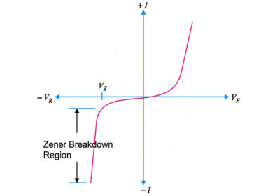
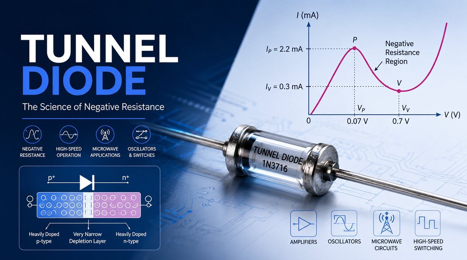
Consideremos la curva I-V del diodo Zener a continuación:
La región directa muestra el aumento exponencial estándar de la corriente del diodo que sigue la ecuación del diodo.
En modo de polarización inversa, la corriente de fuga es pequeña hasta la rodilla de ruptura (voltaje Zener), después de lo cual la corriente aumenta rápidamente mientras el voltaje permanece cerca de VZ.
Un diodo Zener está fuertemente dopado para reducir el voltaje de ruptura inverso. Esto, por supuesto, provoca una capa de agotamiento muy delgada. En consecuencia, un diodo Zener tiene un voltaje de ruptura inverso agudo VZ. Esto se ilustra claramente a partir de la característica inversa del diodo Zener que se muestra en la figura anterior. Observe que la característica inversa cae de manera casi vertical en el voltaje inverso VZ.
Podemos deducir claramente de la curva que ocurren dos cosas cuando se alcanza el VZ.
- La corriente del diodo aumenta rápidamente.
- El voltaje inverso VZ en el diodo permanece casi constante.
Dicho de otra manera, el diodo Zener operando en esta región tendrá un voltaje relativamente constante a través de él, independientemente del valor de la corriente a través del dispositivo. Esto permite que el diodo Zener se utilice como un regulador de voltaje.
La tensión Zener VZ cambia con la temperatura. Los diodos Zener de bajo voltaje, de ~2.4 – 5.6 V, a menudo tienen un coeficiente de temperatura negativo debido al efecto túnel Zener, mientras que los dispositivos de mayor voltaje muestran un coeficiente positivo (dominado por la avalancha). Los fabricantes suelen proporcionar los valores típicos de mV/°C en las hojas de datos.
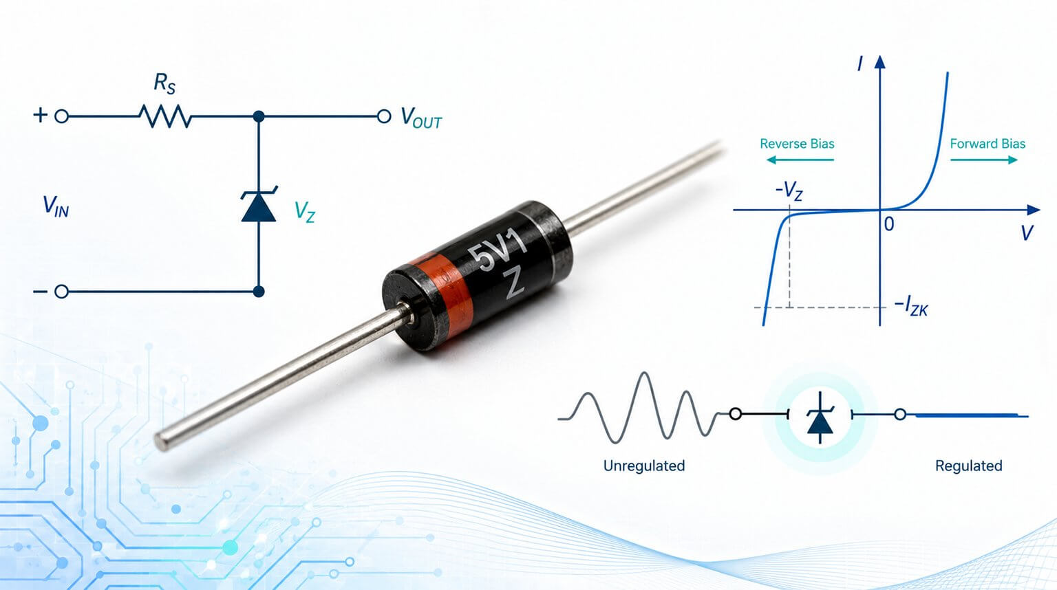
Este es el uso más común, donde el diodo Zener se conecta polarizado inversamente a través de la carga con una resistencia en serie desde la fuente. Cuando el diodo Zener opera en la región de ruptura o Zener, el voltaje a través de él es sustancialmente constante para un gran cambio de corriente a través de él.
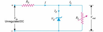
A continuación se muestra un circuito típico de un regulador de diodo Zener:
Siempre que el voltaje de entrada Vin sea mayor que el voltaje Zener Vz, el diodo Zener opera en la región de ruptura y mantiene un voltaje constante a través de la carga. En este caso, la resistencia limitadora en serie Rs limita la corriente de entrada.
Con referencia a la figura anterior, la operación del regulador de voltaje del diodo Zener se puede describir de la siguiente manera:
El diodo Zener mantendrá un voltaje constante a través de la carga independientemente de los cambios en la corriente de carga o el voltaje de entrada. A medida que aumenta la corriente de carga, la corriente del diodo Zener disminuye para que la corriente a través de la resistencia Rs sea constante.
Dado que el voltaje de salida = Vin – IRs y la corriente I es constante, el voltaje de salida permanece sin cambios. Sucederá lo contrario si la corriente de carga disminuye.
Este circuito también realizará correcciones para los cambios en los voltajes de entrada. Si el voltaje de entrada Vin aumenta, fluirá más corriente a través del diodo Zener, aumentará la caída de voltaje a través de Rs, pero el voltaje de carga permanecería constante. Lo contrario ocurriría si el voltaje de entrada disminuyera.
Tiene baja eficiencia para corrientes de carga pesada. Esto se debe a que si la corriente de carga es grande, habrá una pérdida de potencia considerable en la resistencia limitadora en serie.
Además, el voltaje de salida cambia ligeramente debido a las impedancias Zener (Zz) como Vout = Vz + IzZz. Los cambios en las corrientes de carga producen cambios en la corriente del diodo Zener. Como resultado, el voltaje de salida también cambia.
Por lo tanto, la utilización de este circuito se limita solo a aquellas aplicaciones donde la variación en la corriente de carga y el voltaje de entrada es pequeña.
Cuando un diodo Zener se conecta en un circuito para la regulación de voltaje, se deben cumplir las siguientes condiciones:
El diodo Zener debe operar en la región de ruptura o región de regulación, es decir, entre Iz(max) e Iz(min). La corriente Iz(min), generalmente 10 mA, es la corriente Zener mínima para poner el diodo Zener en estado ON, es decir, en la región de regulación. La corriente Iz(max) es la corriente Zener máxima que un diodo Zener puede conducir sin destruirse debido al calor excesivo.
El diodo Zener no debe exceder la potencia de disipación máxima; de lo contrario, se destruirá debido al exceso de calor. Si la disipación de potencia máxima de un zener es Pz(max) y el voltaje zener es VZ, entonces: Pz(max)= VZIz(max), por lo tanto, Iz(max) = Pz(max)/VZ
Existe un valor mínimo de RL para asegurar que el diodo Zener permanecerá en la región de regulación dentro de la región de ruptura. Si el valor de RL cae por debajo de este valor mínimo, el voltaje adecuado no estará disponible a través del Zener para llevarlo a la región de ruptura.
Los diodos Zener se pueden colocar en paralelo con entradas sensibles o rieles de alimentación para limitar los picos transitorios y ayudar a proteger los componentes de condiciones de sobretensión.
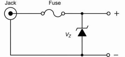
Considere el circuito que se muestra a continuación:
Si se aplica un voltaje excesivo al jack, por ejemplo, a través de una fuente de alimentación enchufable con una clasificación incorrecta, el diodo Zener conducirá hasta que el fusible se funda.
El voltaje de ruptura del diodo Zener debe ser ligeramente superior al voltaje máximo tolerable que la carga pueda soportar.
En este caso, se puede emplear un fusible de acción rápida o lenta, dependiendo de la sensibilidad de la carga.
Las clasificaciones de corriente y voltaje del fusible deben seleccionarse de acuerdo con los límites esperados de la aplicación.
Es importante señalar que otros diseños similares de protección contra sobretensiones utilizan dispositivos especiales, por ejemplo, supresores de voltaje transitorio (TVS) y varistores. Estas alternativas son más baratas y se emplean ampliamente en el diseño de dispositivos electrónicos.
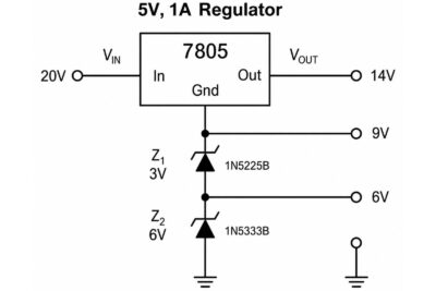
Los diodos Zener se pueden aplicar para elevar el nivel de un regulador de voltaje y obtener diferentes voltajes de salida regulados.
Considere el circuito que se muestra a continuación:
Por ejemplo, en el circuito anterior, se colocan diodos Zener de 3 V y 6 V en serie para elevar la tierra de referencia de un circuito integrado regulador de 5 V hasta 9 V, sumando un total de 14 V.
Es importante tener.
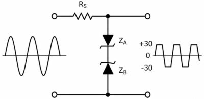
Dos diodos Zener opuestos se pueden usar para recortar ambas mitades de una señal de entrada.
Considere el circuito que se muestra a continuación:
Con referencia a la figura anterior, la onda sinusoidal se convierte en una onda casi cuadrada.
Además de actuar para remodelar una forma de onda, la disposición ilustrada anteriormente se puede colocar en el terminal de salida de una fuente de alimentación de CC para evitar que transitorios de voltaje no deseados lleguen a una carga conectada. Los voltajes de ruptura en ese caso deben ser mayores que el voltaje de suministro pero menores que el voltaje transitorio máximo permitido.
La supresión de voltaje transitorio (TVS) bidireccional y simple también se puede utilizar para lograr el mismo propósito.
Para la regulación de voltaje, elija VZ cercano al voltaje de salida requerido. Para la protección contra sobrevoltaje, elija VZ por encima del voltaje de operación normal pero por debajo del voltaje máximo que la carga puede tolerar de forma segura.
Asegúrate de tener en cuenta la tolerancia y el coeficiente de temperatura, ya que el voltaje Zener real puede variar con la corriente de operación, la temperatura y la tolerancia del dispositivo.
Seleccione una potencia nominal para que la disipación de potencia en el peor de los casos, VZ × IZ(max), se mantenga por debajo de PZ(max), con suficiente margen para la temperatura ambiente y las condiciones térmicas.
Para un voltaje de suministro VS, corriente de carga IL, voltaje Zener deseado VZ y corriente Zener seleccionada IZ, la resistencia en serie se puede estimar como:
RS = (VS – VZ) / (IL + IZ)
Elija IZ para que el diodo Zener permanezca en regulación con la carga mínima y no exceda su corriente máxima permitida con el voltaje máximo de la fuente. Esta corriente puede ser de unos pocos mA para algunos diodos Zener de señal pequeña y mayor para diodos Zener de potencia, dependiendo del dispositivo. Siempre consulte la hoja de datos.
Los diodos Zener suelen producir ruido y tienen una resistencia dinámica finita, por lo que no son ideales para referencias de bajo ruido. Para reducir el rizado, se puede añadir un condensador de derivación en paralelo con el diodo Zener. Para requisitos de bajo ruido o alta precisión, una referencia de banda prohibida o un circuito integrado de referencia de voltaje de precisión suele ser una mejor opción.
Hay una serie de componentes que pueden considerarse como alternativas a los diodos Zener, dependiendo de la aplicación.
- Referencias de banda prohibida: Proporcionan voltajes de referencia estables, a menudo alrededor de 1.2 V, con baja deriva de temperatura y menor ruido. Se utilizan comúnmente cuando se requiere precisión.
- Referencia de voltaje de precisión IC: proporciona mayor precisión, menor deriva y menor ruido que los diodos Zener, pero con mayor costo y complejidad del circuito.
- Reguladores lineales, LDOs y reguladores conmutados: Generalmente se prefieren para una regulación de voltaje eficiente a corrientes más altas.
Utilice un LDO o un CI regulador cuando se requiera una buena regulación de carga, respuesta transitoria rápida, control de habilitación/apagado, apagado térmico, limitación de corriente, arranque suave, secuenciación o una salida estable con un mínimo de componentes externos. Los circuitos simples de reguladores Zener no proporcionan estas funciones.
Ventajas:
- Los diodos Zener son simples, de bajo costo y ampliamente disponibles en muchos voltajes y potencias, lo que los convierte en una buena opción para aficionados que trabajan en proyectos de electrónica sencillos.
- Su pequeño tamaño les permite ser utilizados en circuitos más pequeños.
Limitaciones:
- Los diodos Zener son ineficientes para corrientes de carga moderadas a altas (la regulación en derivación generalmente desperdicia corriente).
- Los diodos Zener tienen una precisión y estabilidad limitadas en comparación con las referencias dedicadas.
- Son dependientes de la temperatura y ruidosos, por lo tanto no son una buena opción para bajo ruido o donde la alta eficiencia es primordial.
Un diodo Zener puede ser un componente pequeño, pero su selección puede afectar la estabilidad del voltaje, la protección del circuito y la confiabilidad a largo plazo del producto. En proyectos reales de PCB y PCBA, comprender cómo funciona el dispositivo es solo el primer paso; usar componentes genuinos y con la clasificación adecuada es igualmente importante.
En PCBCool, apoyamos proyectos de ensamblaje de PCB con abastecimiento de componentes y servicios de revisión de listas de materiales (BOM). Obtenemos componentes únicamente de proveedores autorizados y fiables para ayudar a reducir el riesgo de piezas falsificadas o de baja calidad en la producción.